Conceptual Design of the HF CalorimeterThese pages present renderings from the solid model of the HF calorimeter created as a starting point for discussion. They are developed as an assembly scenario to demonstrate that if the analysis shows that the pieces can take the loads, then there is a process to get the HF assembled. The pictures also direct the design of lifting and postioning hardware, and temporary fixtures necessary to accomplish each step. The moment the HF concept changed from bricks to wedges, certain additional concepts inevitably came along with the wedge idea. I started with the basics of what the internal structure of a wedge looked like, and figured out how it could be lifted. Much of the rest of the conceptual design "fell out" because of gravity. I see the bottom and top halves of the HF as completely different animals because of gravity. What makes sense as a support structure for the bottom half makes no sense for the top and vice versa. Color is used in these pictures mainly to indicate different parts, and does not reflect the actual coloring of the components. Clicking on any of the thumbnails brings up a larger image. You are welcome to download any of the images. If they are used for other than private viewing, credit to Bartoszek Engineering would be appreciated.
Back to the Bartoszek Engineering Home Page |
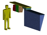 Page 1: Internal structure of a wedge
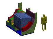 Page 2: Assembly of the wedges on the lower cradle
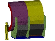 Page 3: Assembly of the concrete and poly on the lower half
 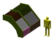 Page 4: Assembly of the top cradle of concrete and poly
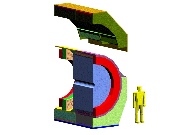 Page 5: Final Assembly