Photos of the early history of E760 at FermilabE760 (now E835) is an experiment in the AntiProton Source at Fermilab to study the charm-anti-charm quark pair (called charmonium). The experiment consists of a hydrogen gas jet target and a group of radiation detectors. The gas jet acts as a fixed target for the beam of anti-protons in the Accumulator to collide against, and the radiation detectors record the particles ejected from the collisions between protons and anti-protons. The gas jet was built by the University of Genova in Italy. The largest detector is the Central Calorimeter, a 10 foot diameter barrel made up of 64 wedges filled with 20 different shapes of lead glass crystal. The calorimeter was built by Fermilab with contributions for the glass from several institutions. Inside the calorimeter are tracking chambers and a cherenkov detector built by the Universities of Torino and Ferrara. The trapezoidal vacuum vessel under the gas jet is the luminosity monitor, designed and built by Northwestern University and Fermilab. Penn State was responsible for building the Forward Calorimeter (not shown in these pictures.) Northwestern also provided an early hodoscope used before the calorimeter was finished. Bartoszek Engineering has been involved with installing and uninstalling the central calorimeter, and in consulting on assembly procedures and fixtures for mounting detectors inside the calorimeter. All but two of these images were taken by Larry Bartoszek while he was employed by Fermilab. You are welcome to download any of the images. If they are used for other than private viewing, credit to Bartoszek Engineering would be appreciated. (Presentation of photos from Fermilab does not imply endorsement of any product or service.)
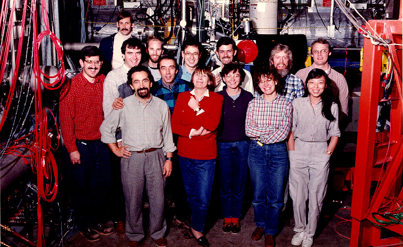
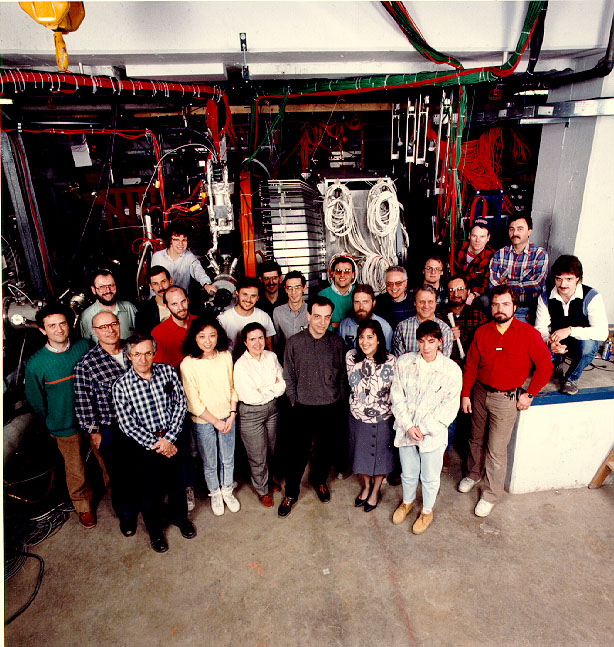
This group photo was taken following the first installation of the hydrogen gas jet target into the beam line of the AntiProton Source Accumulator. Installation had to be staged because of the time it took to build various components.
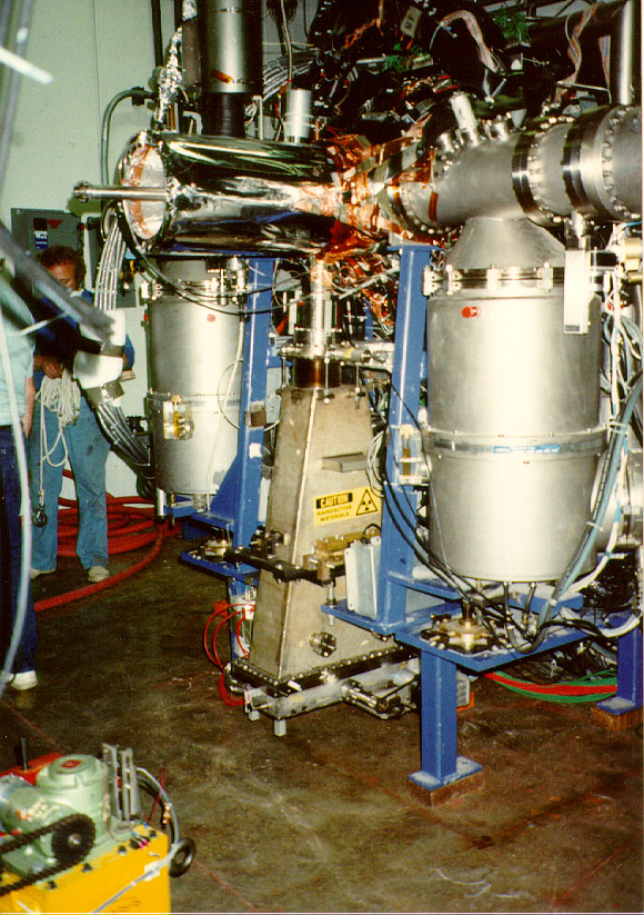
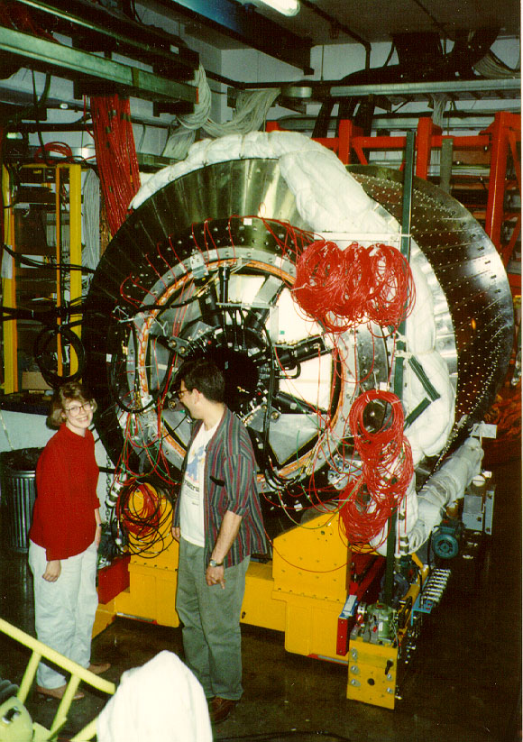
This shows the gas jet standing on its own with some tracking chambers clustered around the beam pipe and the luminosity monitor hanging below. The idea of the gas jet is to send globules of cooled hydrogen from one side of the jet to the other crossing the vacuum pipe of the Accumulator. The immense turbomolecular pumps seen on both sides of the jet are to suck away excess hydrogen that doesn't properly clump so that it doesn't raise the pressure of the Accumulator (an ultra-high vacuum).
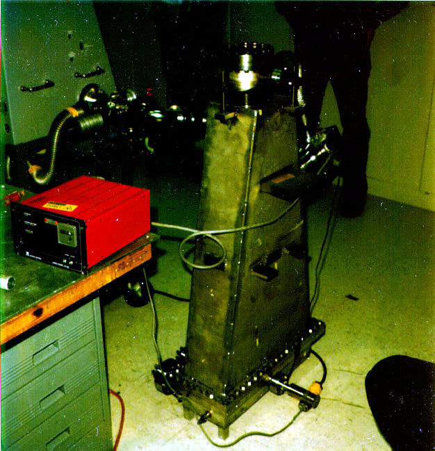
This picture is of the Luminosity Monitor which sits below the gas jet. As anti-protons collide with the protons from the gas jet some particles are scattered through the small hole between the gas jet beam pipe and the luminosity monitor. Most of the volume of the monitor is the upper section, or "horn," which is a vacuum vessel to allow the particles to get to the "oil pan" at the bottom of the device. These particles go to a series of silicon detectors in the bottom of the luminosity monitor where they are measured. The detectors are arrayed in a line as shown in the next picture because the angle that the particle makes with a vertical line (straight down from the collision point) is a measure of the particle's energy.
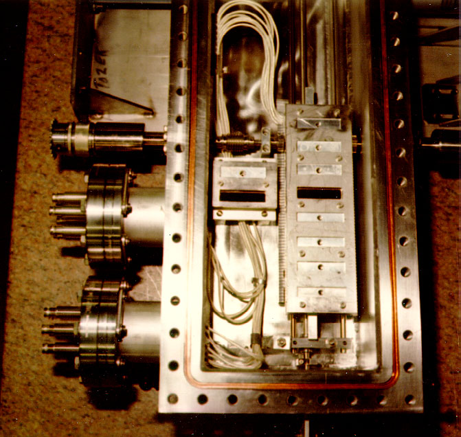
This was the first version of the "oil pan" which had a carriage of detectors mounted on a linear bearing track on one side of the pan and several fixed detectors mounted on the other. In this picture, only one slot on the movable carriage and one on the fixed side actually have silicon drift detectors in them. The rest are aluminum dummies to allow the cover plates to be attached. it was later redesigned to put the moving carriage in the center of the pan. The carriage is driven by a stepper motor outside the vacuum vessel turning a rotary vacuum feed-through which rotates a pinion gear on a rack. The motion is encoded by a similar arrangement on the other side of the carriage feeding rotary motion out of the vacuum to a rotary encoder outside the vessel.
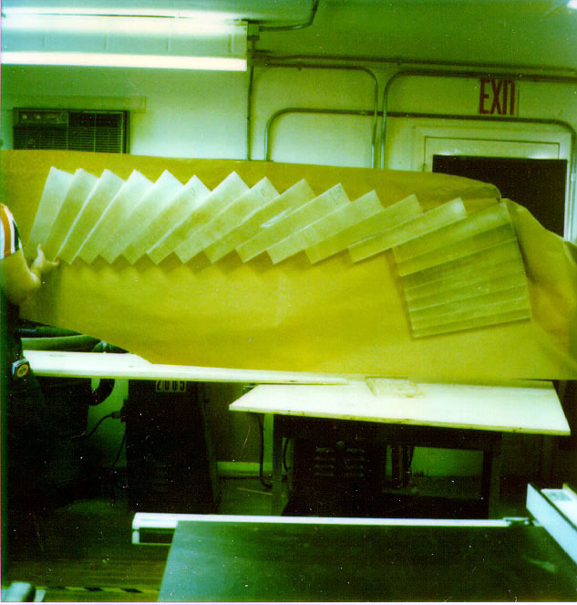
It was originally hoped that we could fabricate the wedges for supporting the lead glass out of epoxy fiberglass because of its transparency to radiation. The test shown was made by wrapping aluminum patterns simulating the glass blocks with glass tape and painting them with epoxy. The blocks were then laid up on a table designed to compress the wedge into shape by vacuum bagging the wet lay-up. The table could be heated to cure the epoxy faster. After many different techniques were tried we gave up on epoxy because of lack of good control over tolerances and insufficient strength. When building a barrel out of 64 wedges even a few thousandths of an inch oversize on each one can mean that the wedges may not line up with their support hardware. Ultimately, the wedges were made from thin stainless steel.
Phase I was an installation of the experiment designed to try out all the detectors except the central calorimeter, which wasn't ready yet. It allowed commisioning of detectors and made the experiment ready for the arrival of the calorimeter. We never took a group photo around the central calorimeter because after it was installed their wasn't room for everyone and a place to stand to take the picture.
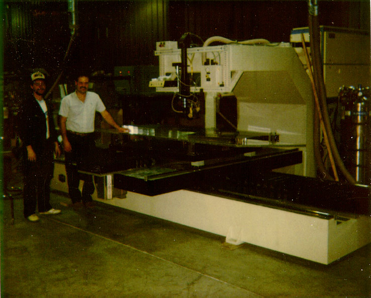
The final design for the wedges to support the lead glass was to make the partitions between blocks out of .010" thick stainless steel sheet and the side walls of the wedges out of .030" thick stainless sheet. The partitions were laser cut with small tabs on their edges and the side skins were laser cut with small slots. The tabs were manually inserted into the slots and tack welded, then fully welded with the laser. The ends of the wedge which interfaced to the support structure were made from 1/2" thick stainless and we developed the technique for welding .030" thick sheet to 1/2" thick plate. This work was done at Laser Machining, Inc, in Somerset, WI.
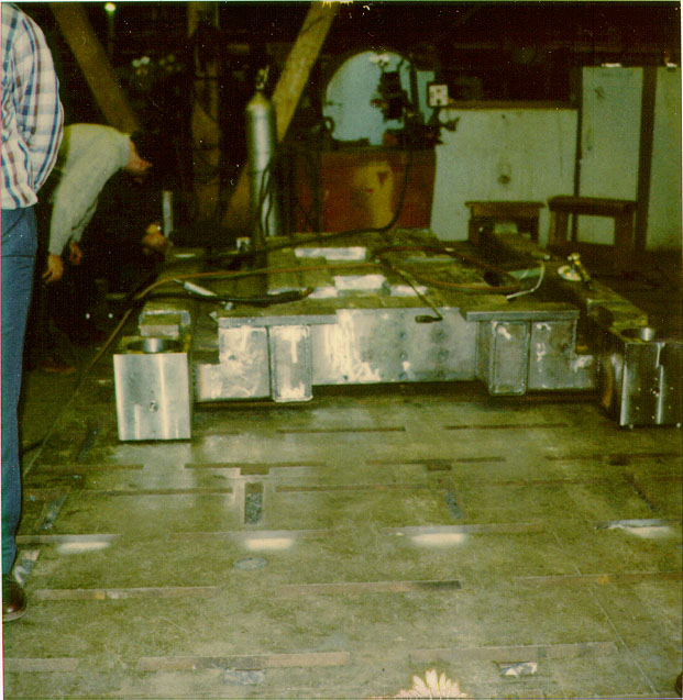
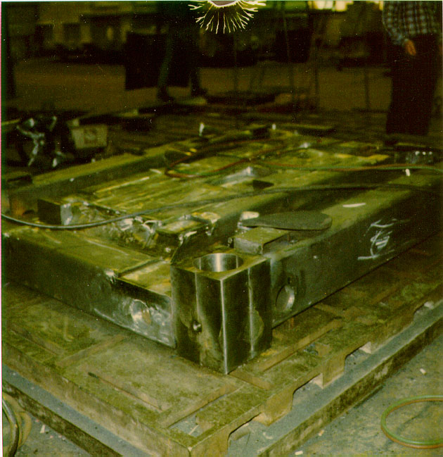
This picture was taken on an inspection trip to Whiting where the steel base of the central calorimeter was fabricated. The base has a complex contour to create pockets where drive mechanisms could be mounted to align the calorimeter to the beam line.
This picture shows a closer view of the many steel tube sections that went into fabricating the support base.
This picture shows the Central Calorimeter fully assembled and in the E760 assembly area adjacent to the Accumulator beam. The cherenkov and H2 hodoscope can also be seen in the center of the calorimeter. The Central Calorimeter is moved around the assembly area on air casters, and has mechanisms to adjust its position in space in all six degrees of freedom. It also has a fork-lift-like mechanism to support the gas jet and precisely pull it into the opening of the calorimeter. The only mechanism we have never needed to test is the mechanism to rotate the whole barrel of glass around its axis for repair. In the life of the experiment (since 1987), out of 1280 photomultiplier tubes glued onto the lead glass blocks only one or two have failed. Cable connections have been the biggest source of lost signals.
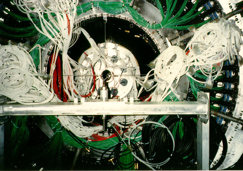
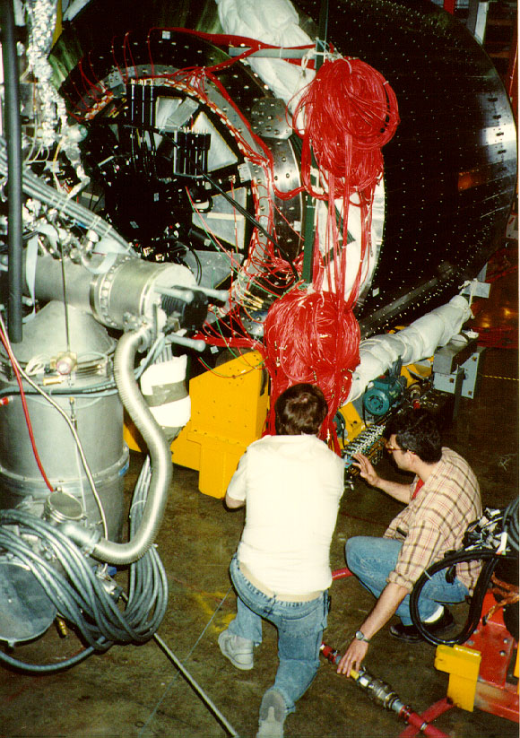
The downstream end of the central calorimeter is where all the high voltage and signal cables come out of the wedges and get routed to the data acquisition system. The aluminum structure in the foreground is a temporary beam pipe support. It is attached to the same beams that support the gas jet during insertion which allows the jet and beam pipe to move smoothly into place without extra tension or compresssion from the supports. This is very important because the beam pipe coming out of the gas jet is only .008" thick.
This is a picture of the upstream end of the calorimeter base showing several alignment mechanisms. The flange and hydraulic cylinder next to the corner block is one of the pushers arrayed around the base to push the calorimeter off the walls or brackets mounted to the floor. This system controls the yaw and two degrees of horizontal translation. The corner blocks contain screw jack assemblies which control the roll, pitch and elevation of the calorimeter. Because the horizontal pushers act while the calorimeter is standing on its jack, they were design to absorb side load. You can also see the air casters under the base that allow the calorimeter to float around the assembly area. The calorimeter is floating in this picture.
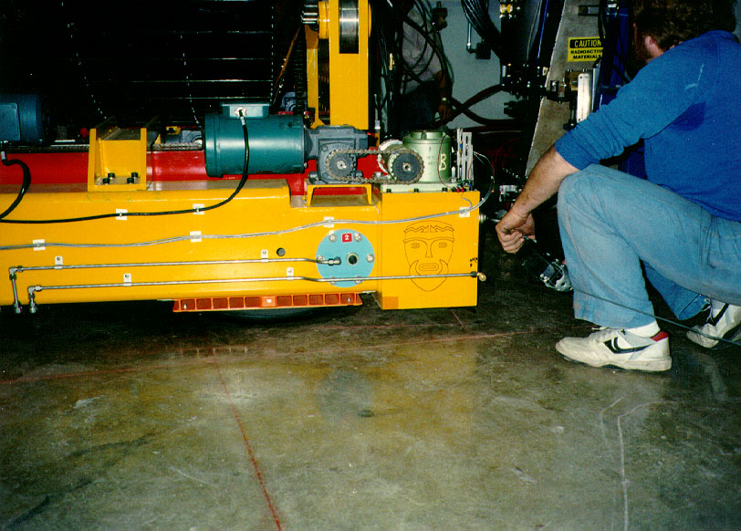
We are moving the calorimeter on its air casters in this picture to get it around the cable support structure in the tunnel. this series of moves was carefully choreographed in CAD to make sure that it was possible as the clearances in critical areas were only inches. It is possible for one person to move the calorimeter when it is floating, but slope in the tunnel floor forces us to use several people and restraining winches.
Back to the Bartoszek Engineering Home Page
|