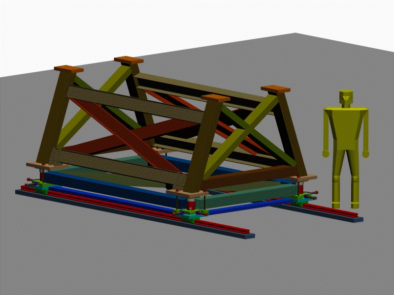
Design of the Modified G0 Carriage as of 9/3/01Bartoszek Engineering is currently contracted to redesign the original G0 carriage we designed and had built some years ago. The need at Jefferson Lab is to be able to move the spectrometer in and out of the beam-line, so Jefferson Lab engineering people proposed the addition of a lowest layer of THK linear bearing rails. These bearings would support the spectrometer and can theoretically allow it to be moved off beam-line without disturbing its internal alignment. The degrees of freedom of the original structure have been preserved in this redesign. The redesign comes from the fact that the existing carriage lower frame would interfere with and not connect to the new bearing rails. The pictures that follow present the development of the design as it would be installed in Hall C at Jefferson Lab, starting with grouting the THK rails to the floor. It is hoped that members of the G0 collaboration and Jefferson Lab personnel will examine this design and give approval to continue the design into manufacturing drawings. Click on any of the thumbnails to get an enlarged view. You are welcome to download any of the images. If they are used for other than private viewing, credit to Bartoszek Engineering would be appreciated.
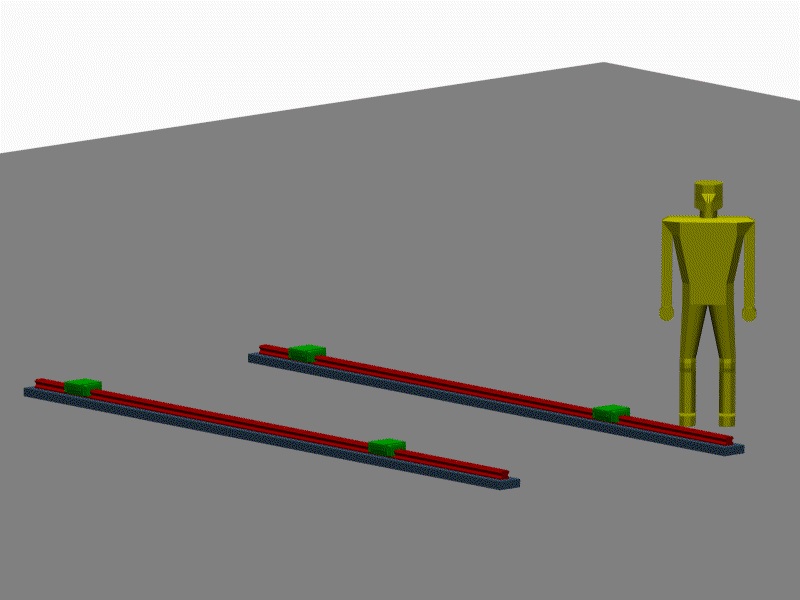
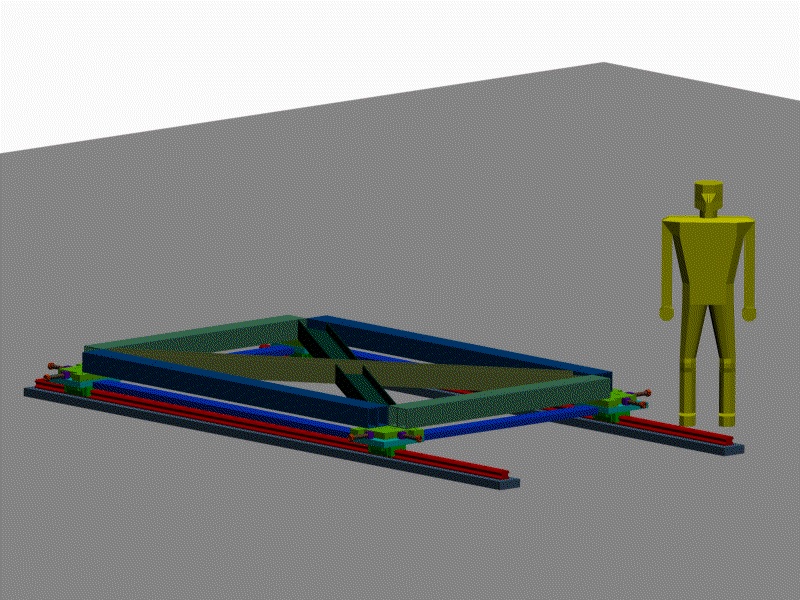
Rails mounted to the floor of Hall C
This picture shows the THK bearing rails mounted to plates grouted to the floor of Hall C. The green blocks are the THK pillow blocks. The rails are not shown at full length, as that is to be determined.
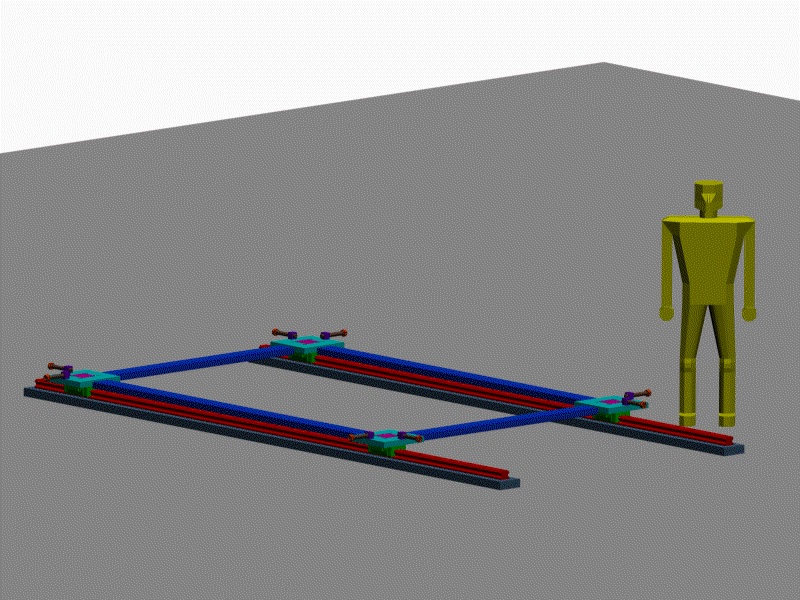
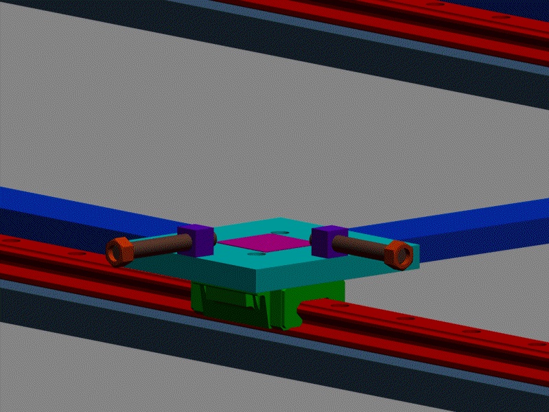
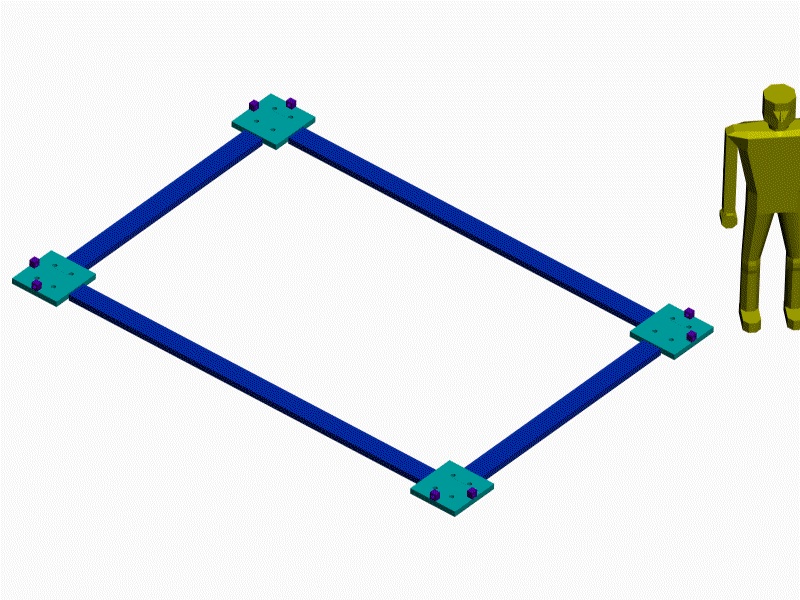
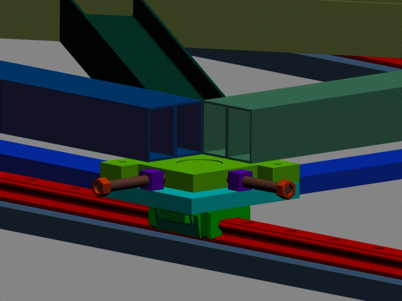
The Bearing Frame
This frame serves the purpose of holding the individual THK pillow blocks in place with respect to each other, and providing the fixed points for horizontal adjustments to push off from. It is a new frame fabrication. The magenta plate in the middle of the cyan aluminum plate is a DU pad that allows the next layer up to slide horizontally with respect to this layer. This is an existing part and can be reused, as can the horizontal threaded rods. The purple blocks that support the threaded rods are welded to the cyan plates. The third picture in the top row shows the frame as a bare weldment.
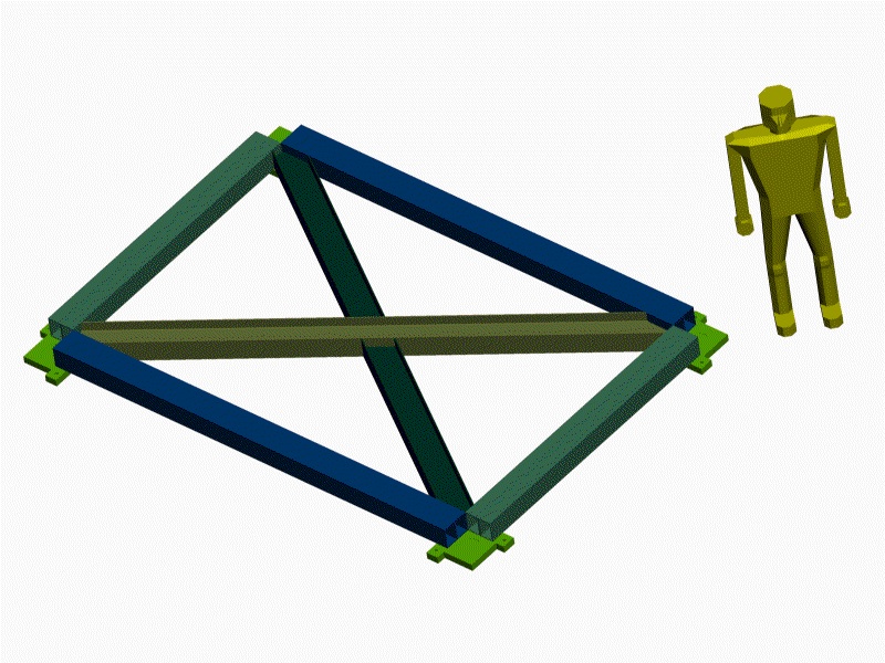
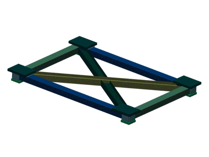
The Intermediate Frame on the Bearing Frame
The next frame up is the layer that is pushed horizontally and contains the vertical adjustment for the spectrometer (not shown). As can be seen below, the Intermediate frame can be made from the current Lower frame at NPL by cutting the corner blocks off and welding on new corner plates, or it can be made new if there is no time when the existing Lower Frame is not needed to support the spectrometer.
A picture of the existing Lower Frame.
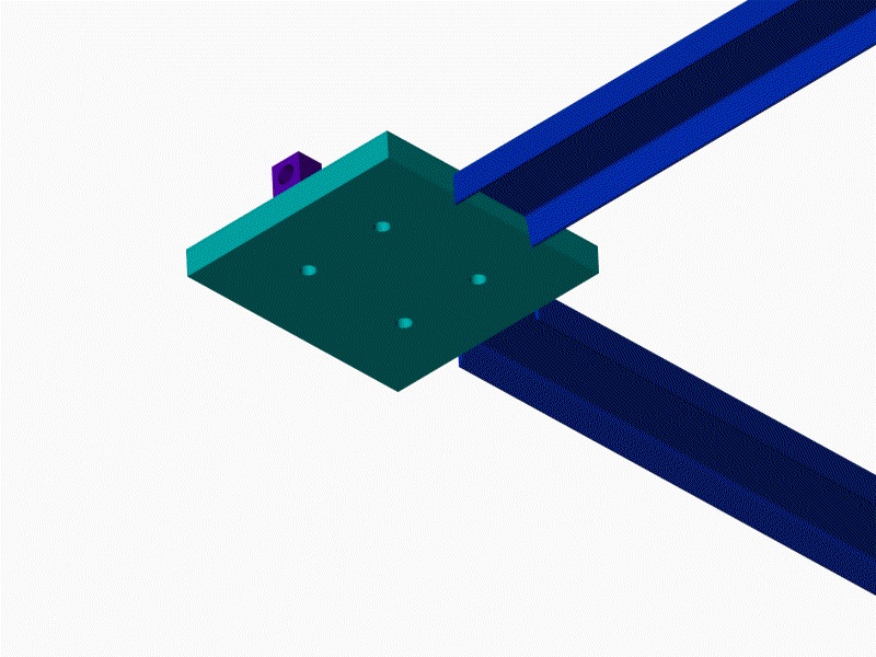
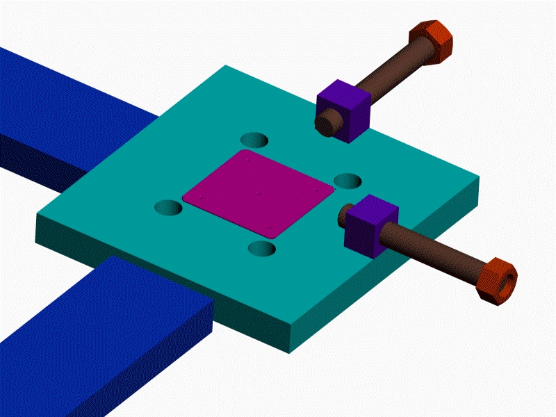
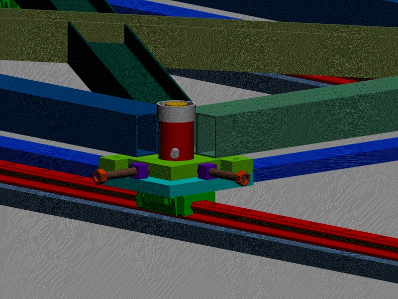
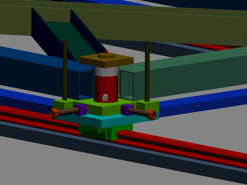
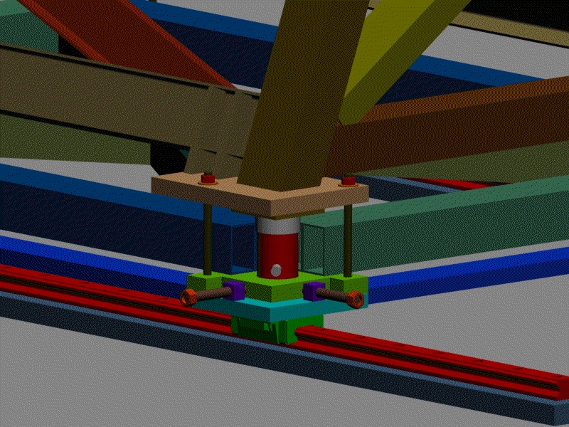
Vertical, Roll and Pitch Adjustment by Hydraulic Cylinders
These pictures show the OTC hydraulic cylinders that will support the upper frame of the spectrometer carriage. These cylinders have a threaded collar which is tightened after alignment to carry the load. The hydraulic pressure is then bled from the system avoiding the possibility of leaks and changing alignment during the run. The system is designed to run at 10,000 psi, easily implemented in 3/8" OD stainless tubing routed along the framework. (See the E760 page for pictures of a similar system mounted on the E760 calorimeter for horizontal adjustment.)
The upper frame requires no modification. The shim pack and spherical plain bearing are removed and replaced with a plate shown in the top row second image. (This plate is actually attached to the upper frame prior to assembling the upper frame to the hydraulic cylinders.)
The main advantage we see in this design is that two of the adjacent (NOT diagonal) hydraulic cylinders can be connected together and powered from a single supply tube. This converts the four-point stand into a three-point stand because the other two cylinders are individually powered. A simple manual control valve manifold (not shown) adjusts the amount of oil in the pair of connected cylinders and each individual cylinder by routing oil from a single hydraulic pump. The pump could be a hand operated manual pump. This arrangement was designed into the original frame, but with temporary cylinders supporting the spectrometer until the correct shims could be installed in each corner. This design is much more elegant in that the shims become the threaded collar on the cylinders, which is the equivalent of a variable shim with extremely fine resolution. Another nicety of this design is that the line of action of the cylinders and the threaded collar is the same, the axis of the cylinder, which wasn't true in the earlier design as the cylinders were offset from the shim packs.
After alignment, the threaded rods on both sides of each cylinder are tightened, locking the upper frame to the lower for seismic considerations.
We believe this design to be far superior and much safer than a motorized screw jack design that is inherently a four-point support and has no equivalent way of becoming a three-point support. Most of the existing structures and adjustment features can be reused in this design saving cost over an all new fabrication. Back to the G0 Main Menu Back to the Bartoszek Engineering Home Page |