Photos of the first Collimator Module AssemblyThe images below were taken during the assembly of the first collimator module in the barn at the Nuclear Physics Lab, University of Illinois, Urbana-Champaign. The aluminum plates for the structure of the collimators were manufactured at Anderson Tool & Engineering, Inc, in Anderson, IN. All of the fasteners are made of aluminum, and were custom fabricated by Decatur Bolt. The most significant problem Bartoszek Engineering solved in the design of the collimators was the structure's ability to absorb the differential contraction between the aluminum and lead which occurs as the collimators are cooled from room temperature to liquid helium temperature. The lead wants to contract by about twice as much as the aluminum does. The solution was to design two different types of bolted connections. On each block of lead a single fastener attaches the lead as an anchor in a tight fitting counterbored hole in the aluminum. The other one or two bolts attaching a block are able to move toward the anchor bolt because the aluminum plates were slotted around their counterbores. These slots create a connection which is soft in one direction in the plane of the plate, and rigid in the others, including out-of-plane rigidity. The slotted connection is called a "spring beam" connection. The red structures, called "toasters", were fabricated by the Civil Engineering shop at UIUC. The toasters are assembly and shipping fixtures that were necessary because the collimators can only be supported by the same surfaces that allow them to be bolted to the octagon rings in the G0 cryostat. Assembly of the collimators was accomplished by a crack group of technicians and undergrads at UIUC, including Andy Kenyon, Eric Thorsland, and John Blackburn.
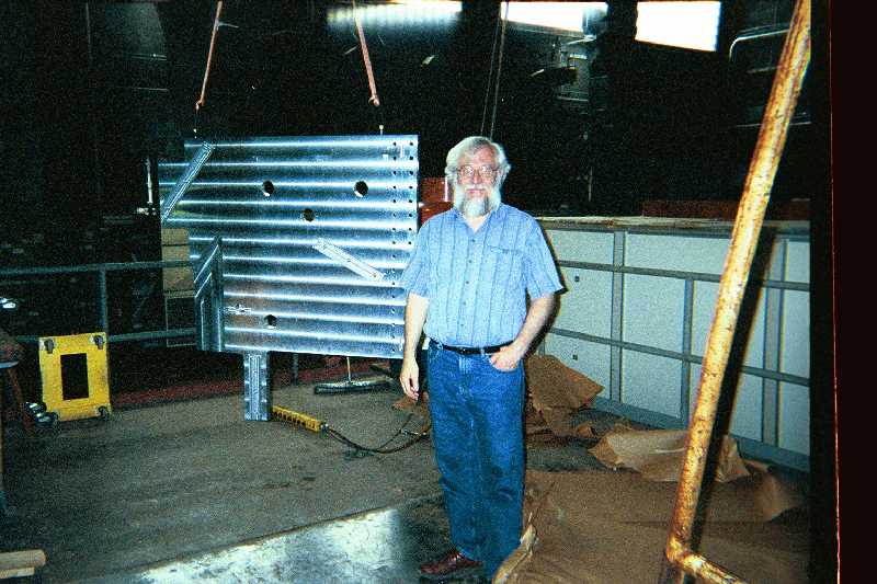
Ron Laszewski, the designer of the G0 spectrometer, stands next to a side plate of the first collimator. The first piece to be attached to the toaster was the "top hat", onto which all the other collimator pieces are attached. Side plates act as flanges in the box structure that carries the weight of the lead out to the octagon rings. This one is being readied for cleaning to vacuum standards.
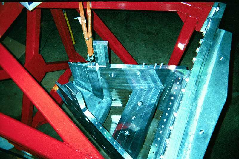
Clearances on the LOS-LP block had to be carefully considered because it only goes into the wedge shaped structure of the collimator one way and is trapped by edges of the aluminum plates. By properly lifting it from three points on its "top" surface, the block's edges are aligned to the bottom edge of the side plate and it slips in with no trouble at all. Solid modeling determined the correct location of the pick points to achieve the alignment.
Azimuthal collimator blocks look flat on their exposed surfaces, but in reality the surface which determines the azimuthal acceptance of the collimator is a warped surface. AutoCAD's Mechanical Desktop was essential in creating the solid which the shape was made from. A NURBS surface was first created to the warped specification and then a prismatic solid was cut with this surface creating the finished part.
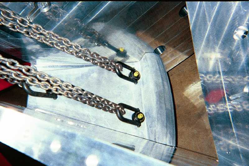
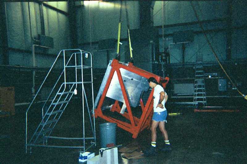
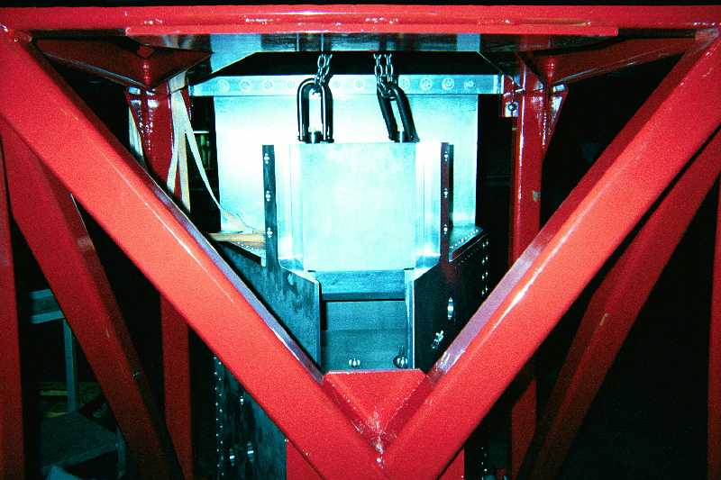
The toasters were designed to be rotated onto either end to allow the installation of the lead blocks from both ends. Rotations were accomplished by lifting the toaster from a point on it which caused it to rotate in air once the bottom left contact with the floor, allowing it to be set down in the desired configuration. The pick point had to be moved when sufficient lead was added to the structure, which was done by choking slings on different points.
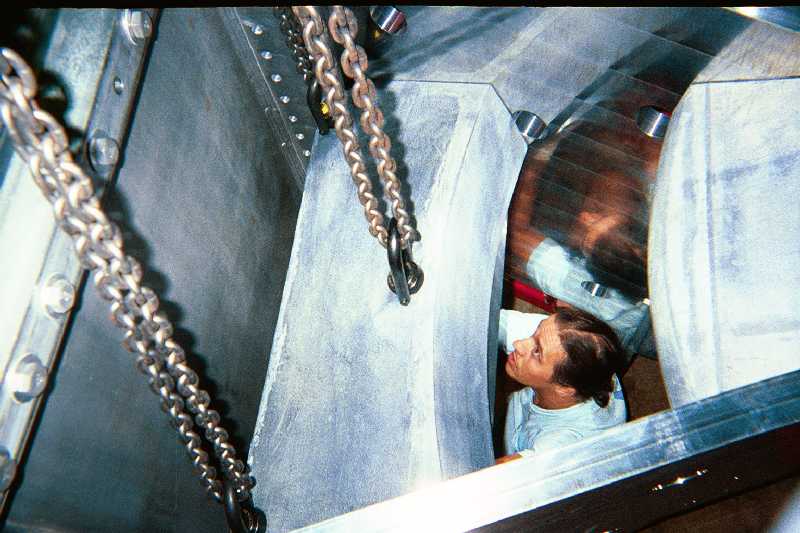
Eric Thorsland is under the aluminum plate which the upper primary collimator block is attached to. The block is bolted to this plate from behind by three 1" diameter aluminum bolts. The center bolt is the anchor bolt, the other two are spring beam connected. Drilling fixtures were used to accurately locate tapped holes in the lead blocks which custom keyed inserts were installed into. The custom inserts have tapped internal holes for the aluminum bolts. We tested the entire design by immersing a lead block/aluminum plate assembly into a vat of liquid nitrogen.
After the azimuthal collimators are installed, the upstream end plate can be installed with its already attached block of lead, and the block 1-2 support plate. Once this plate is installed, block 1-2 can be lowered into place and attached.
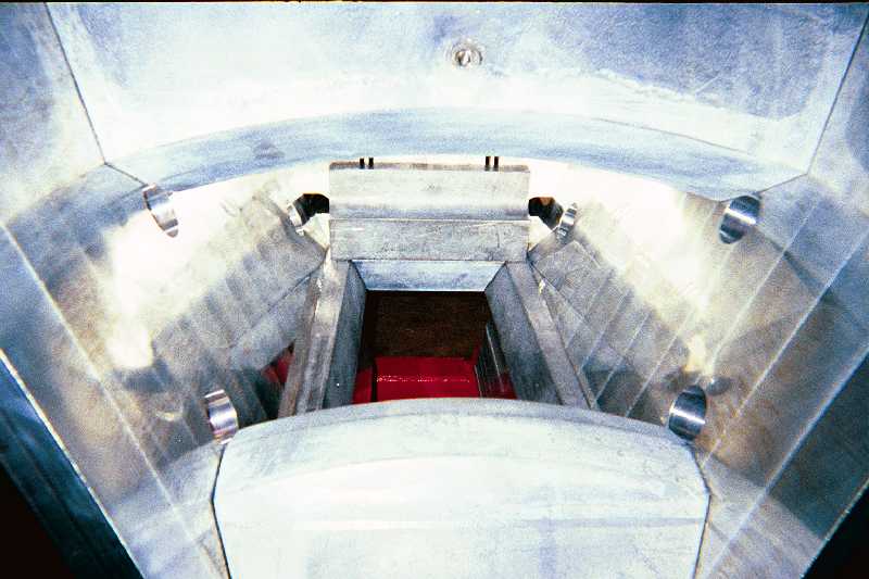
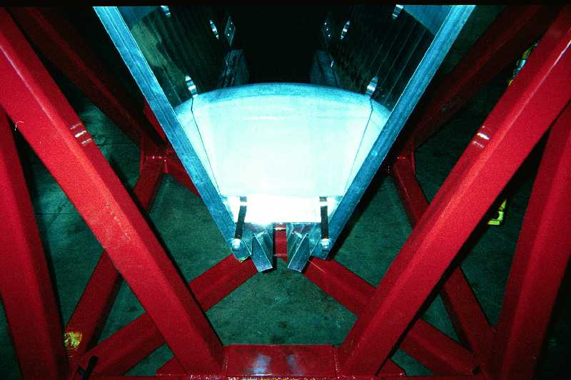
This view looks into the aperture toward where the target will be located in the finished spectrometer. The collimators were designed to select radiation from the target to allow through the vacuum windows to the detectors and to lower the background noise from rejected radiation.
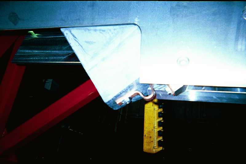
This view shows the two copper straps that were designed to aid in conductively cooling the mass of the lead blocks. The blocks could only be attached to the aluminum at a few points to avoid differential contraction stress, and in a vacuum these connections may not be good thermal conductors. The cooling straps were added to increase the area in conductive contact with the aluminum so that the lead will cool faster and will not lag behind the aluminum at a much higher temperature.
This view shows the two cooling straps on the downstream end of the LOS-LP block. Even though this block is about the same weight as the upper primary collimator block, it has three straps because it is farthest away from the heat extraction points on the collimator and only connected by two bolts.
This is the third cooling strap on the LOS-LP block to maximize its heat extraction. Notice the loops in each of the strap designs to prevent the strap's thermal contraction coefficient from causing stress on the aluminum and lead.
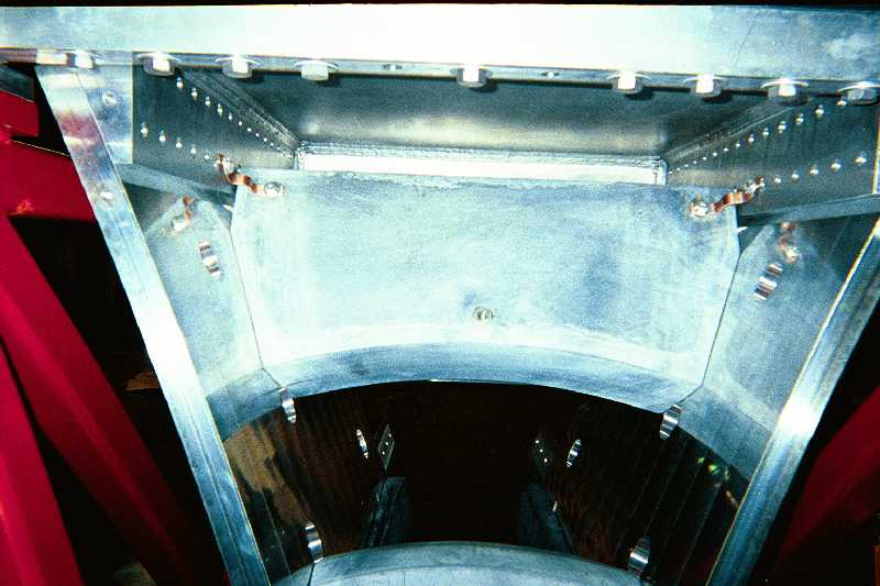
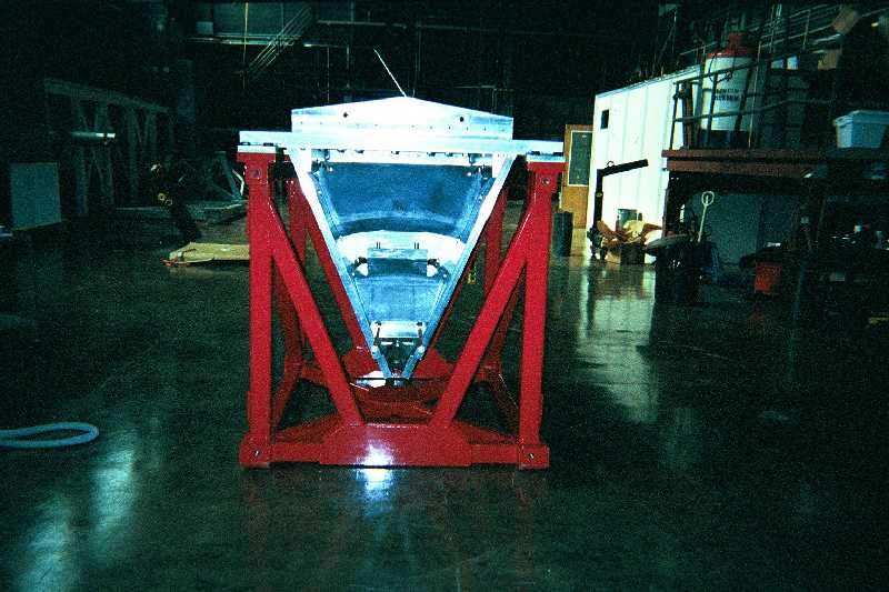
This is a view of an assembled collimator sitting on its toaster. The only things remaining to be done are to attach PT-100 temperature sensors, install videogrammetry targets, and package it for the trip to BWXT where it will be installed into the spectrometer.
Another view of the first almost-finished collimator.
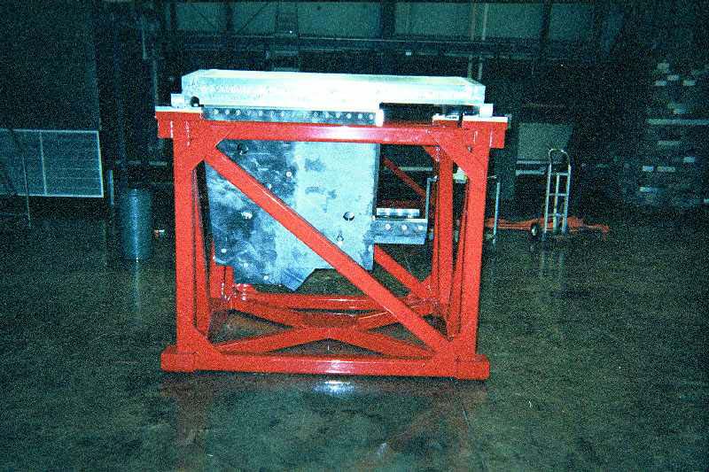
A side view of a completed collimator.
Back to the G0 Main Menu
Back to the Bartoszek Engineering Home Page
|