Rendered images of the Reference Conceptual Design for the G0 ExperimentThe images below are renderings of the solid model that was created by Bartoszek Engineering for the G0 experiment. The G0 spectrometer is made up of eight superconducting magnets with collimation modules between the magnets to reduce background. The main purpose for the model was to understand the routing of the cryogenic plumbing in the spectrometer and check for interferences between the collimators and superconducting coils. Coloration was also used to understand the flow paths in the thermosiphon loops. The images were created at different stages of the design process, so elements like the spectrometer support structure do not reflect the current design. All designs shown are from the Reference Conceptual Design of the spectrometer and do not represent the final design of the device. Photos will be added as the experiment is built. You are welcome to download any of the images. If they are used for other than private viewing, credit to Bartoszek Engineering would be appreciated. Most of these images were created with AutoCAD R12 and AccuRender 2.1 from an AME solid model of the G0 spectrometer design. Images of the collimators had to be done with AutoCAD R13 and the Mechanical Desktop because AME was unable to represent the complex contoured surfaces of the collimator blocks.
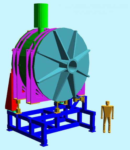
The can above the cryostat is a reservoir for liquid nitrogen and liquid helium. It is also the feed can for the superconducting power leads. Notice the flat heads on the ends of the cryostat. These were required to allow the detectors (not shown) to be as close to the magnets as possible.
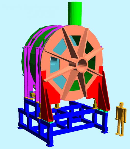
This view looks into the large vacuum windows on the downstream head which let the radiation out of the spectrometer and into the detector packages. Detectors are not shown because they are not completely designed yet. These openings will be closed with a thin kevlar/mylar or metal vacuum window.
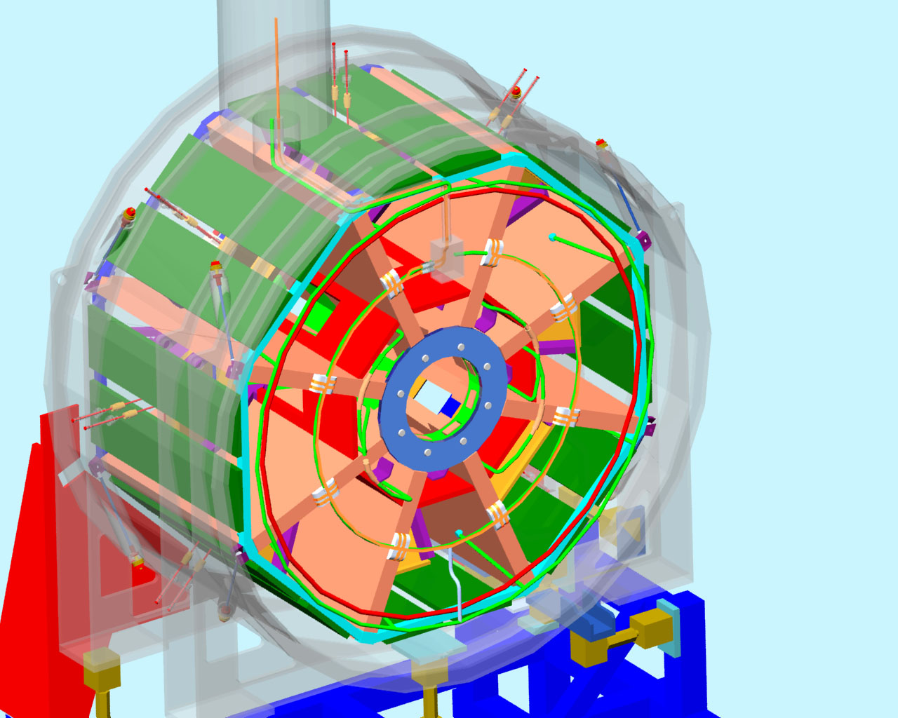
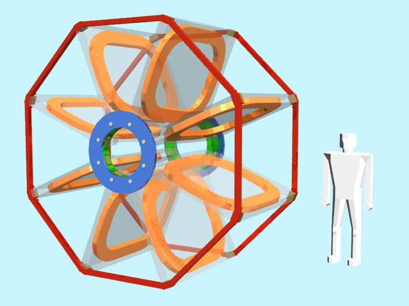
In this view the stainless steel cryostat vacuum vessel has been rendered transparent to allow you to see into the fully assembled spectrometer. The liquid nitrogen shield has been left out to simplify the image.
The downstream view through the transparent cryostat shows the contoured blocks of lead in the collimation modules (green, yellow, and salmon colored blocks). Particles in the desired momentum and energy range pass between the lead blocks and exit the spectrometer through the vacuum windows in the downstream head. Their passage is recorded by plastic scintillating paddles (not shown) which convert some of their energy into light. The light generated by the scintillator is collected in photomultiplier tubes.
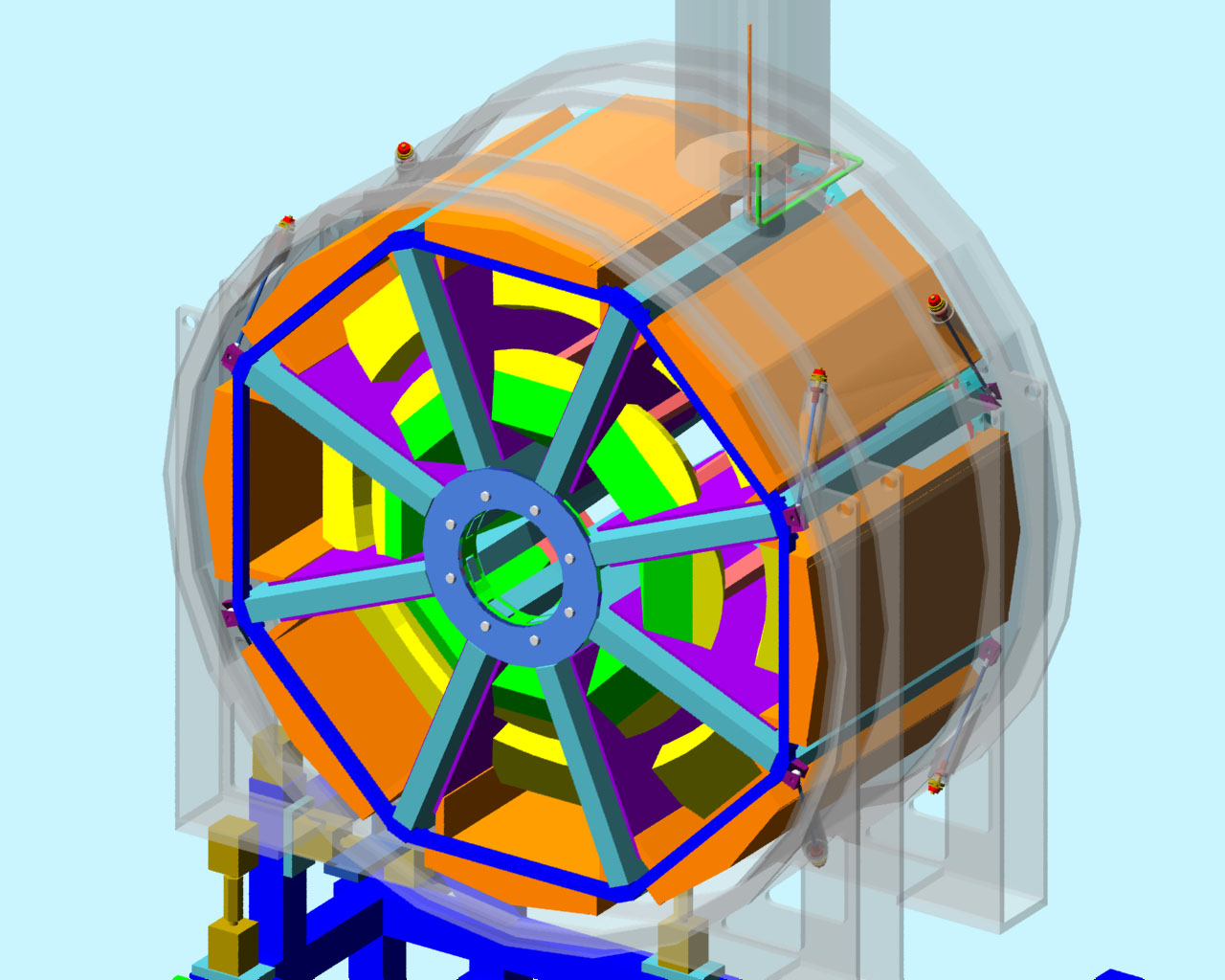
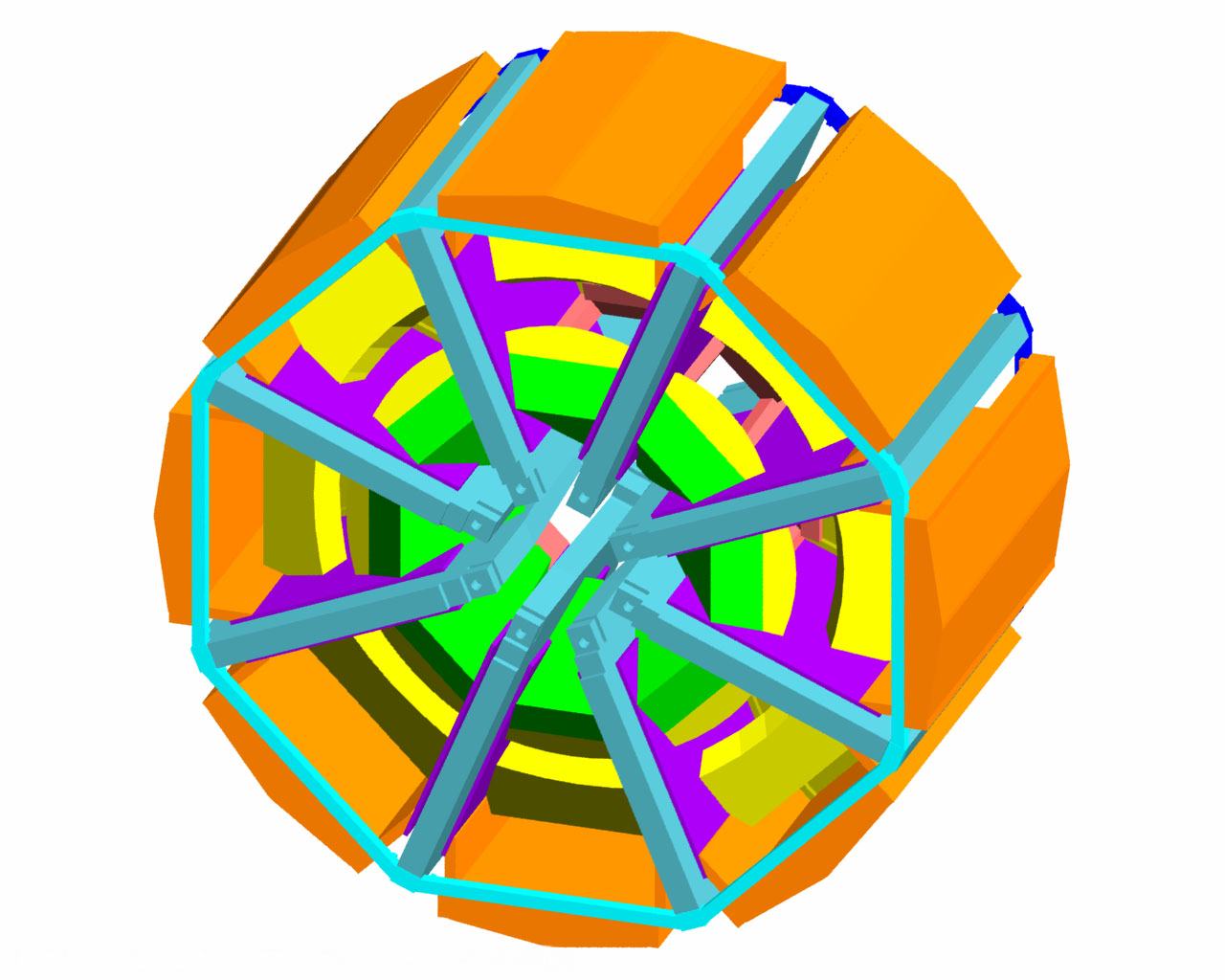
This image shows the structural members which support and align the eight superconducting coils. The structures are all aluminum and are designed to allow a single coil to be postioned while the rest are locked in place. The aluminum coil cases have been made transparent to view the superconducting cable inside.
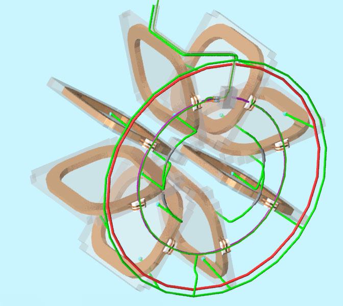
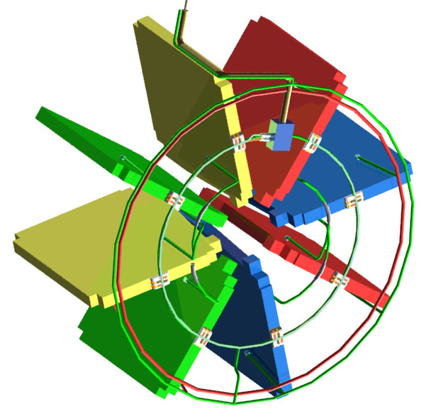
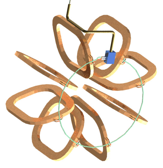
This image and the following one were created to visualize the complex flow circuits between the eight superconducting magnets. Liquid helium is supplied by the cryo-reservoir atop the vessel. The bottom four magnet coils are fed the liquid helium first by the supply manifold. The lower four coils are each connected to an upper coil to make four parallel thermosiphon loops.
Coils of the same color are connected in series between the supply and return liquid helium manifolds. Four colors indicates four parallel paths. The inner most loop is the path that the superconducting power lead follows and is cooled by its own liquid helium circuit.
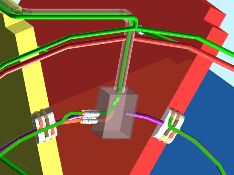
This figure shows the conceptual design of the junction box where the superconducting power leads go out of the LHe return line and enter the vacuum space for routing to the coils. This box needs to be designed large enough to make the cable splices. To seal the vacuum and LHe from each other, the superconducting cable has a copper plug soldered to it that is soldered into the stainless steel outside end of a ceramic feed-through. The ceramic is needed for electrical insulation between the supply and return cables.
This picture shows only the superconducting cable routed throughout the toroid. The supply cable feeds the magnet on the left side of the top octant first and each cable is connected to the previous one counterclock-wise in this view. The return cable from the last magnet is routed back to the junction box over the supply cable to cancel out the magnetic field of the supply cable loop.
This image shows an early design of the collimation modules assembled between the coils on the octagon rings. The hubs which take the magnetic forces from the coils are not shown to expose the Line-Of-Sight shields and the inside surfaces of the modules.
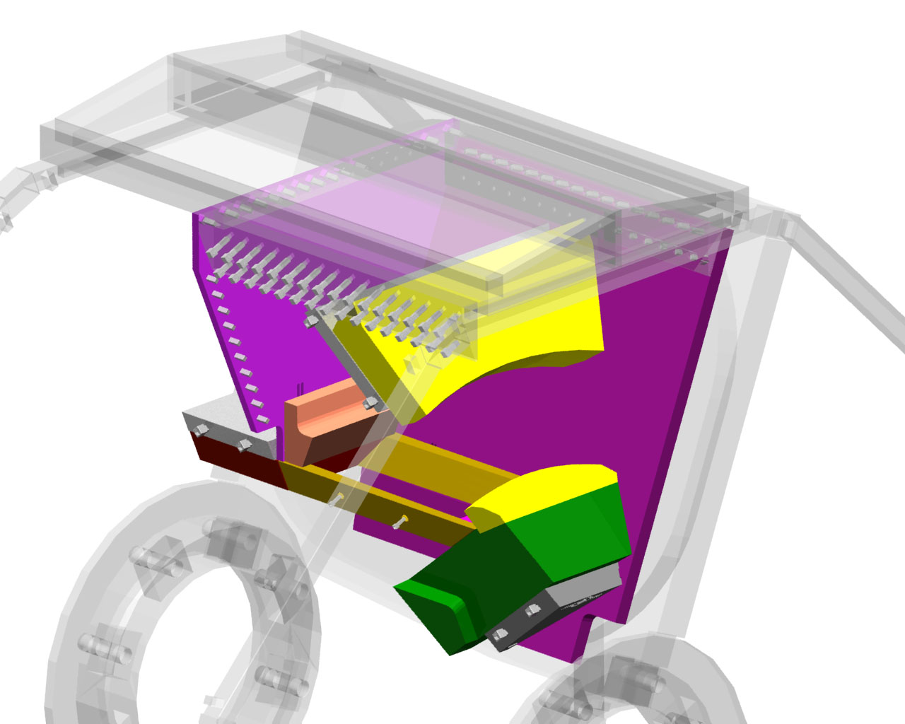
A collimator is a collection of lead blocks supported on an aluminum frame that has precisely contoured apertures to allow particles of the right energies to make it to the detectors outside the cryostat while absorbing as much background as possible. The major technical problem to solve in this design was how to prevent severe thermal contraction stresses from building up. Lead shrinks by about twice as much as the aluminum between room temperature and liquid helium temperature. The problem was solved by cutting slots in the aluminum support plates around some of the fasteners to allow them to move closer to other fasteners which act as anchor points. (Fasteners in this image look square because the facet resolution in the AutoCAD model was not set high enough for good rendering.)
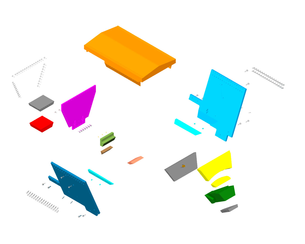
This picture is an exploded view of a single collimator. AutoCAD AME was unable to model the complex curved surfaces on the several collimator blocks, but AutoCAD R13 and the Mechanical Desktop modeled them with no trouble. The curved surfaces of the primary collimator blocks are portions of elliptical conical surfaces.
Back to the G0 Main Menu
Back to the Bartoszek Engineering Home Page
|