Photos of casting the lead blocks for the G0 ExperimentThe pictures below show the process of casting the lead used in the collimator modules of the G0 spectrometer. The pictures focus on the Line-of-Sight (LOS) shield block, but are typical of the process for any of the blocks. The LOS shield weighs approximately 1100 lbs. All of the lead was cast with a calcium lead alloy called MFA 906 + Al. This alloy comes from the Doe-Run Co, and is about three times stronger than chemical lead. It casts very nicely with far less dross than traditional calcium leads without the aluminum stabilizer. The molds are made from patterns which were CNC cut at CasTech from composite materials. The shapes were modeled by Bartoszek Engineering using AutoCAD R13 and the Mechanical Desktop 1.2. The models were then exported to the IGES neutral file format, and e-mailed to CasTech. Programmers at CasTech made the CNC tool pathing files from the IGES files directly. We verified the process by measuring the first two prototype patterns by coordinate measuring machine (CMM). The first patterns were found to be within .010" of the ideal solid model, but the finals were made even closer by holding the parts more rigidly during cutting. The shape of the lead was originally determined at its operating temperature, 4.5K (liquid helium temperature). This meant that all of the patterns had to be scaled up to correct not only for lead shrinkage during casting, but for thermal contraction during cooldown of the spectrometer. You are welcome to download any of the images. If they are used for other than private viewing, credit to Bartoszek Engineering would be appreciated.
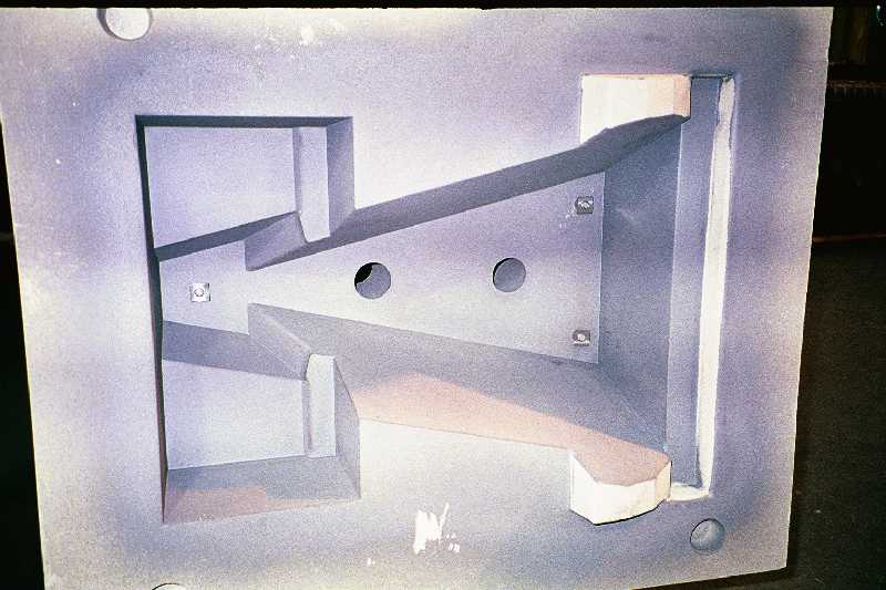
This picture shows half of the sand mold for the Line-of-Sight Shield being readied for assembly with the other half prior to lead pouring.
The molds are called "air-set" sand molds, which means they are made of sand that is bonded together with a high temperature epoxy resin. They are much more economical in that they do not require a steel flask surrounding them, they are self-supporting. Stainless steel tapped inserts are added to the inside of the molds to allow handling of the finished part by hoist rings during assembly.
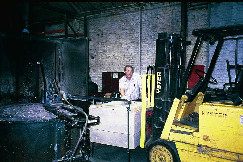
This picture shows the lead pump filling the mold cavity for the LOS mold. The pump is driven by compressed air and at full speed pumps lead at gallons per second.
The lead pump is a very simple machine, but critical to high productivity.
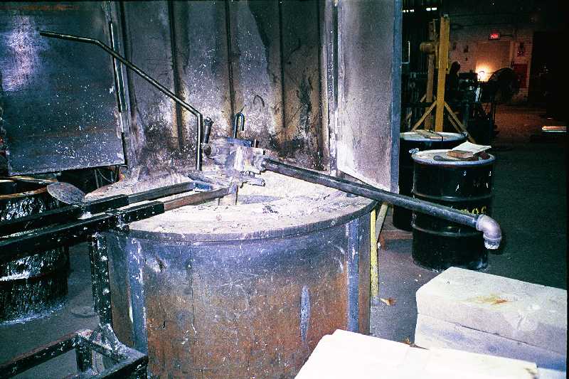
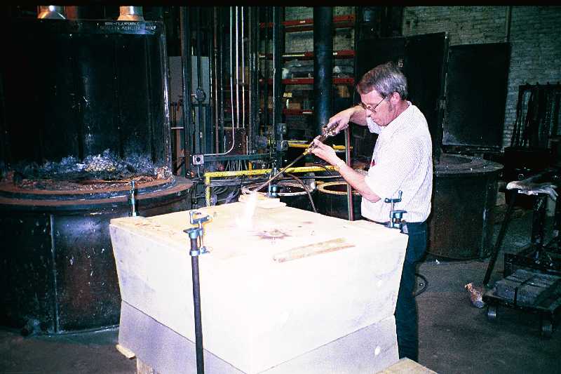
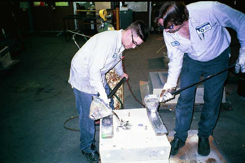
Steve Gamel of Vulcan uses an oxy-acetylene torch to heat the lead in the gates at the top of the mold. This operation insures that the gates stay liquid so that as the lead inside the mold solidifies and shrinks more lead can be added to prevent casting voids.
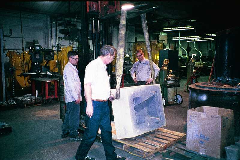
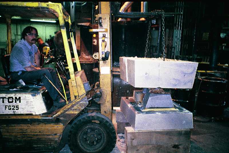
The top half of the mold is removed by forklift. Each of the lead shapes in the collimators had different mold designs, so the exact mold release process for each varied. For example, the upper primary collimator block had a vertical part line. This mold had to be opened sideways using completely different handling techniques.
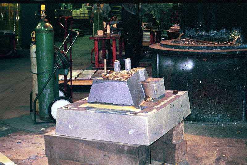
The cylinders sticking up from the surface of the block are made of lead that froze in the gates. Each of the lead blocks needed to be cleaned up of sprues, flash, and other unwanted lead attached to the block. The gate sprues were sawed off with a saws-all and then routered smooth.
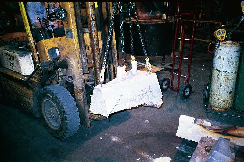
The cast-in inserts come into play here as the block is moved into the cleaning area by chains fixed to these inserts. The inserts are made of 316L stainless steel that was selected for particularly low magnetic permeability. This requirement came from the need to eliminate any magnetic material inside the G0 spectrometer cryostat, and was difficult to meet. The inserts were made at D.K. Precision in Schaumburg, IL, and they had great difficulty finding 316L bar at Chicagoland steel distributors that was non-magnetic. The test we devised was deceptively simple. If a small high field permanent magnet could attract a small chunk of the material then it was not acceptable.
This mold made the Upstream Block 1-2 and shows how the smaller blocks were filled by hand. The same technique using the oxy-acetylene torch was used here to keep the gates open during solidification.
Back to the G0 Main Menu
Back to the Bartoszek Engineering Home Page
|