Pictures and Drawings of the MiniBooNE Horn Body Design, updated 11/2/03Images on this page focus on the design of the body of horn design MH1. Some of the key features of the body of the horn are determined by the fact that the main body of the horn carries the current, so all connections must be capable of carrying 170+ kA. The horn body must seal the radioactive cooling water sprayed around inside the horn. The body of the horn must allow for the expansion of the inner conductor during heating from the current pulse, and absorb the magnetic field pressure. It must handle these stresses well below the allowable stress limits for aluminum fatigue at 200 million cycles. Almost everything in the horn body is aluminum 6061-T6 with a few exceptions noted later. All fasteners in the horn are also aluminum 6061-T6. All penetrations through the outer conductor are standard NW25 and NW50 vacuum ports sealed with EVAC aluminum rings. The upstream end of the horn, shown in the fourth picture down, is the end that the stripline is connected to. This means that this end of the horn sees the largest voltage potential difference. The nominal ground of the outer conductor is isolated from the high voltage input connection of the outer conductor by a ceramic spacer, the orange ring in the fourth picture. The downstream end of the horn is the connection between the flexible end cap and the outer conductor. This bolted flange uses a custom rectangular cross-section dead soft aluminum gasket to seal water and it is plated with silver to carry the full current across the interface. I have eliminated the spider pictures from this page and moved them to a separate page to discourage people from using them in presentations. We built the spider components but never installed them in the horn. The horn has been running for over 50 million pulses at the time of this writing and shows no sign of ever needing spiders. (Please stop using those pictures in public presentations!) Click on the thumbnails to get an expanded image. You are welcome to download any of the images. If they are used for other than private viewing, credit to Bartoszek Engineering would be appreciated.
I've taken the liberty here of removing some ancient and very out of date renderings in favor of some newer ones. Any reference to the spiders has been moved to this page. If anybody needs any other renderings of the horn, please just let me know. I can produce anything required.
If you have the Whip! plug-in from Autodesk, clicking on this thumbnail will launch the plug-in and allow you to view the complete CAD drawing in detail.
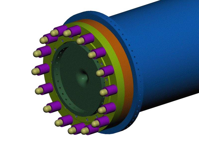
The orange piece is a ceramic ring that voltage isolates the outer conductor from the inner at the upstream end of the horn. The threaded rods that mechanically fasten the two together are completely surrounded by ceramic to prevent arc-over.
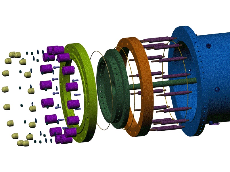
This picture shows the details of the parts which connect the upstream end of the horn. The thin rings are custom aluminum seals made by EVAC. This view also makes the various pieces of ceramic around the threaded rods more obvious. The yellow hemispherical pieces on the left side of the picture are corona caps for the threaded rods to prevent arc-over to the high voltage surfaces of the stripline connection.
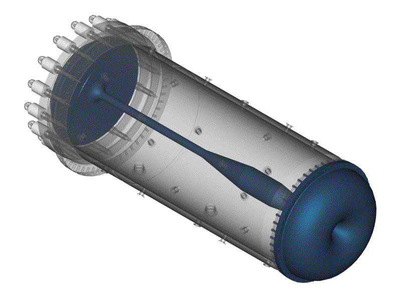
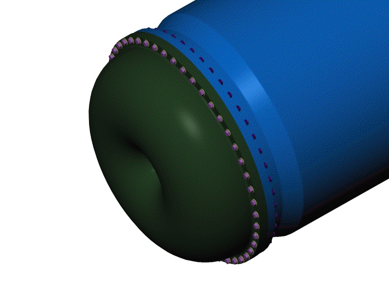
This view shows the numerous bolts that are used to fasten the toroidal end cap to the outer conductor. The design of this flange connection was derived from concepts in Bickford's "An Introduction to the Design and Behavior of Bolted Joints," Third edition. The primary concepts embodied in the joint are to maximize the stiffness of the joint and minimize the stiffness of the bolt, and to minimize prying action on the bolt by the flange moment. Minimizing the stiffness of the bolt is accomplished by making the bolt out of aluminum. Doing this stiffness minimization causes the stress fluctuation seen by the bolt to be minimal, an aid to increasing fatigue life. The flange moment is reduced by making the bolt circle as close to the gasket and line of action of the joined cylinders as possible. The custom aluminum gasket is crushed in an o-ring groove inside the flange and the flanges are tightened metal-to-metal. This allows the joint stiffness to be dominated by the flanges and not the gasket as is typical in most common gasketed joints.
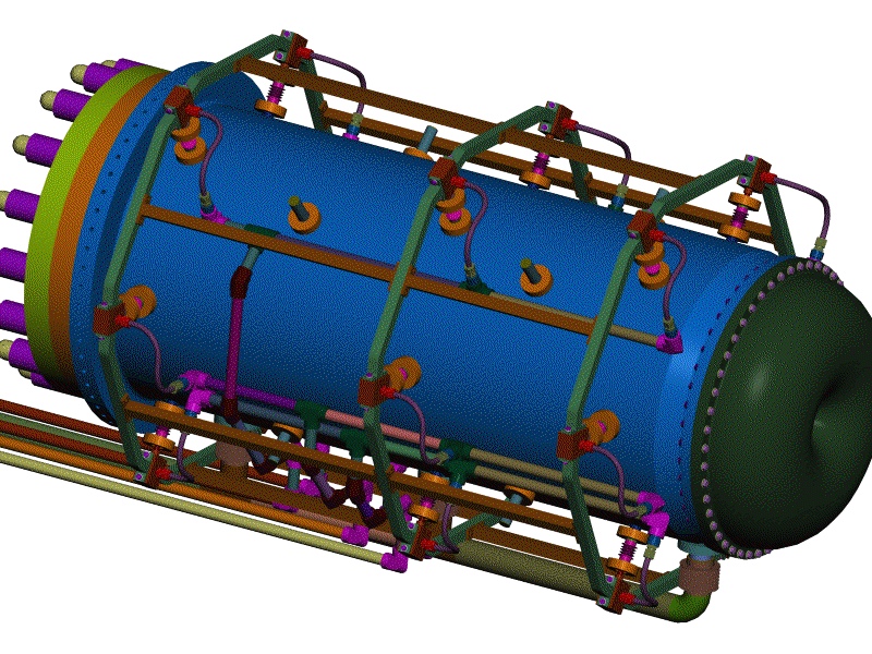
This view shows all the water utilities routed around the horn. These pictures are the most current on the water system, but the change over pictures shown in the water system page is minimal.
Back to the Horn Renderings Main Menu
Back to the MiniBooNE Horn Main Menu
Back to the Bartoszek Engineering Home Page
|
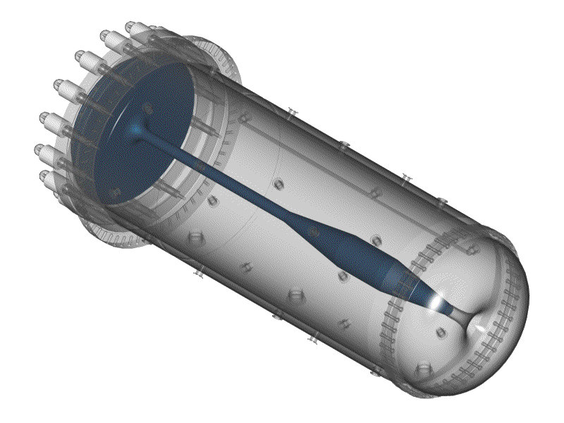
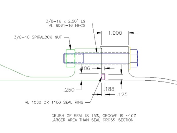 This shows the details of the custom rectangular aluminum o-ring at the downstream end of the horn.