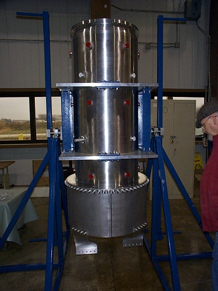
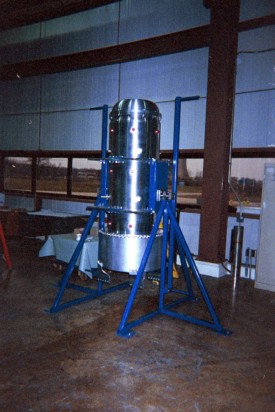
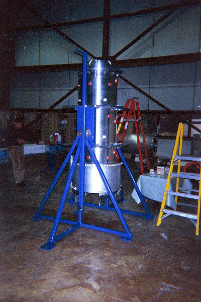
Photos of Test Assembling the OC and End cap at MI-8The following pictures show the test fitting and assembly that happened at MI-8 through 12/4/00. The purpose was to make sure that the rotating fixture worked as designed, the OC fit it, and the end cap fit the OC before the end cap was welded to the rest of the inner conductor. We also tested the crane handling of the end cap using the welding fixture flange that will allow us to lower the whole inner conductor into the outer conductor. Everything went together very well and we were all satisfied with the fits between things. The first assembly of the rotating fixture and outer conductor.
The purpose of the rotation capability built into the assembly stand is to allow us to measure the length of the inner conductor in both orientations with respect to the outer conductor. In the end cap down configuration the end cap is extended outward by the weight of the inner conductor sitting on it. This would make the IC look short with respect to the OC. When it is flipped so that the IC is hanging from the end cap, the IC will stretch the end cap and look long with respect to the OC. By averaging these measurements, we should be able to cut the adapting flange which connects the IC and OC so that the end cap is in a relatively stress-free state.
Without the inner conductor, we could only test fit the ground half-shells and twist transitions. While some deviations from ideal were measured, they look small enough that deflection and moving the parts around within the clearance of the bolt holes will allow things to connect together. The real fit up happens in January after we get the horn box.
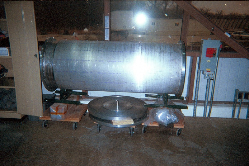
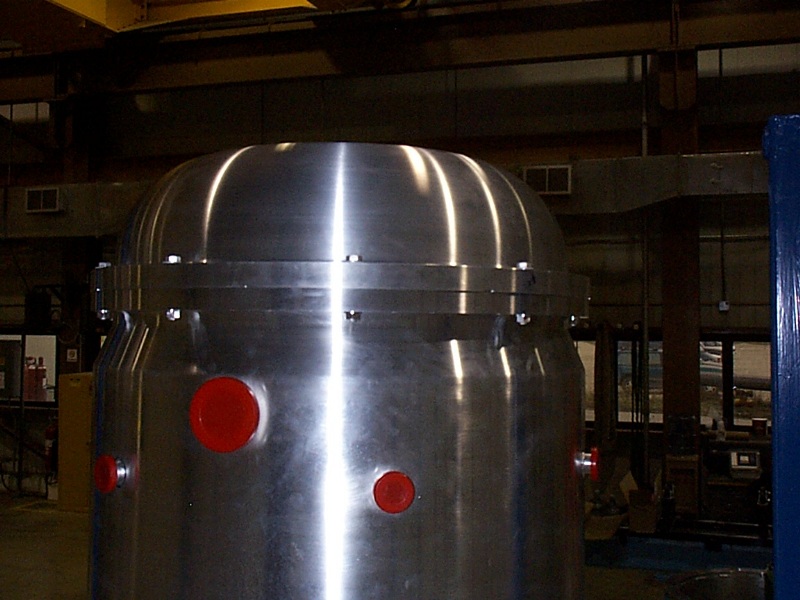
This fixture is necessary to weld the inner conductor together. The end flanges hold the two last pieces of the inner conductor to the welding machine, and the semi-cylindrical shells protect the finished part from bending during handling operations. The end cap flange also serves as the crane handling fixture for the whole finished inner conductor. As the next pictures show, we used it as a lifting fixture with just the end cap.
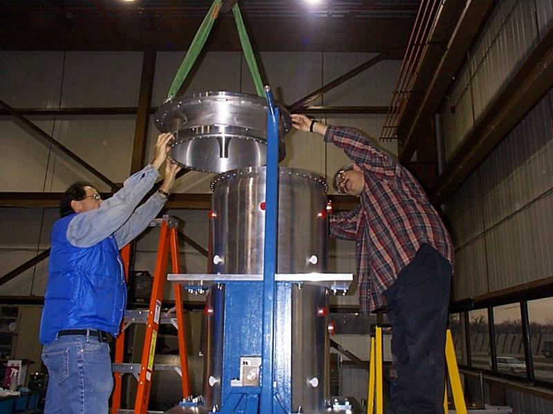
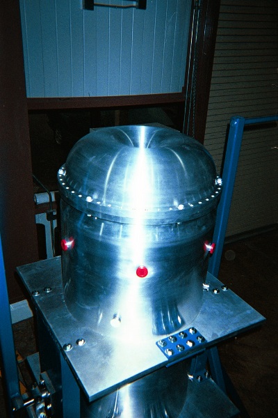
This picture gives you an idea of what the inner conductor will look like hanging with the end cap and welding fixture from the crane in MI-8.
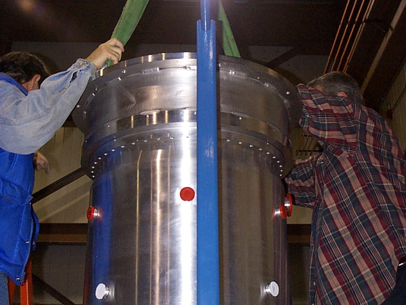
With the real innner conductor this positioning will be impossible as the IC would have crashed into the OC, but it worked fine as a test.
One of the nice features about working on a shorter horn is that you don't have to climb very far up a ladder to do something at the top.
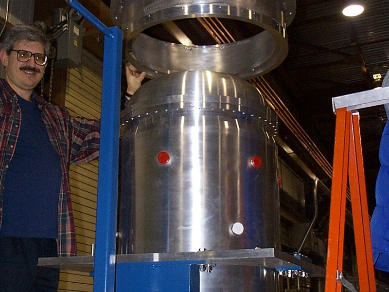
Touch down on the OC. The end cap fit like a dream around the flange on the OC. Cheers to both Pride and Meyer Tool.
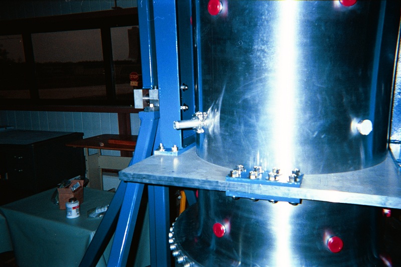
One of the concerns that we had was that the welding/handling fixture might pull the end cap up off the OC while craning the handling fixture away from the assembly. This did not happen, but we are going to do a slight modification to the weld flange to make lining it up and putting the first couple of bolts in easier.
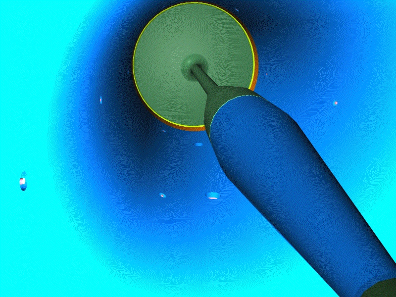
This is what an assembled spider port will look like from the outside.
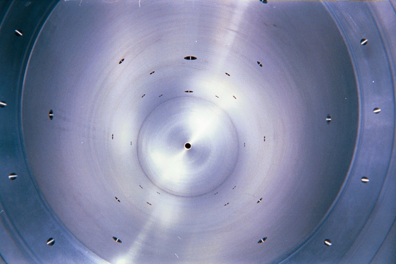
This is a view similar to the rendering on the water page, but looking from the upstream end to the downstream, without most of the IC in place. You can see the ports for the water spray nozzles, the spiders and the drains (the larger holes at the top of the image).
Back to the MiniBooNE Horn Main Menu
Back to the Bartoszek Engineering Home Page
|


