|
Conceptual design of the Krasnoyarsk Weak Mixing Angle Experiment Work done up to 6/28/05
These pictures are renderings of the solid model BE has created of the conceptual design of the Krasnoyarsk Weak Mixing Angle Experiment currently being explored. The Krasnoyarsk WMA experiment is a reactor-based neutrino experiment designed to measure the weak mixing angle parameter, sin theta w. The experiment is conceived to be located under a mountain near a reactor in Krasnoyarsk, Russia. The purpose of this page is to get the pictures and Powerpoint presentations up on the web for interested parties to grab the images they need for presentations and cost estimating efforts.
The Krasnoyarsk Detector is basically a scaled down version of the Braidwood detector. BE has worked on the Braidwood Experiment and is grateful for all of the design ideas that have been adapted to the Krasnoyarsk detector. In particular, the work of Hans Jostlein and Ang Lee of Fermilab, and Vic Guarino of Argonne National Laboratory is acknowledged and appreciated here. Much was also learned from the SNO experiment, and I am also indebted to Art McDonald of SNO for information about the construction of the SNO acrylic sphere. It is hoped that the Krasnoyarsk experiment can act as a prototype for the Braidwood experiment to work out concepts and design ideas for the larger detector. BE learned about the construction of steel spherical vessels during our work on the MiniBooNE Experiment at Fermilab.
The construction scenario presented here has been developed for the Braidwood detector and may need to be changed for conditions at the Krasnoyarsk site. The Braidwood detector is conceived to be built and filled with oil on the surface and craned into the tunnel enclosure. Krasnoyarsk is more similar to the SNO experiment in the sense that both Krasnoyarsk and SNO are both located underground with very limited aperture access tunnels. The Krasnoyarsk detector will have to be segmented into part sizes that can make it through the corridors in the mountain at Krasnoyarsk. It is currently unknown (by BE at least) whether the hook height required by the final assembly shown here can be achieved in the Krasnoyarsk assembly hall.
This design shows an acrylic vessel surrounding the fiducial volume because that is the design being pursued at Braidwood and is the one BE is most familiar with at present. BE is also exploring the possibility of a nylon or Teflon balloon for this central volume, similar to the KAMLAND experiment. We will decide which technology to use based on cost and deployment issues.
Click on any of the thumbnails to get an enlarged view. You are welcome to download any of the images. If they are used for other than private viewing, credit to Bartoszek Engineering would be appreciated.
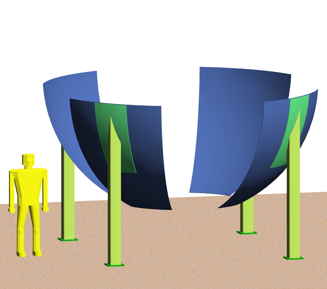
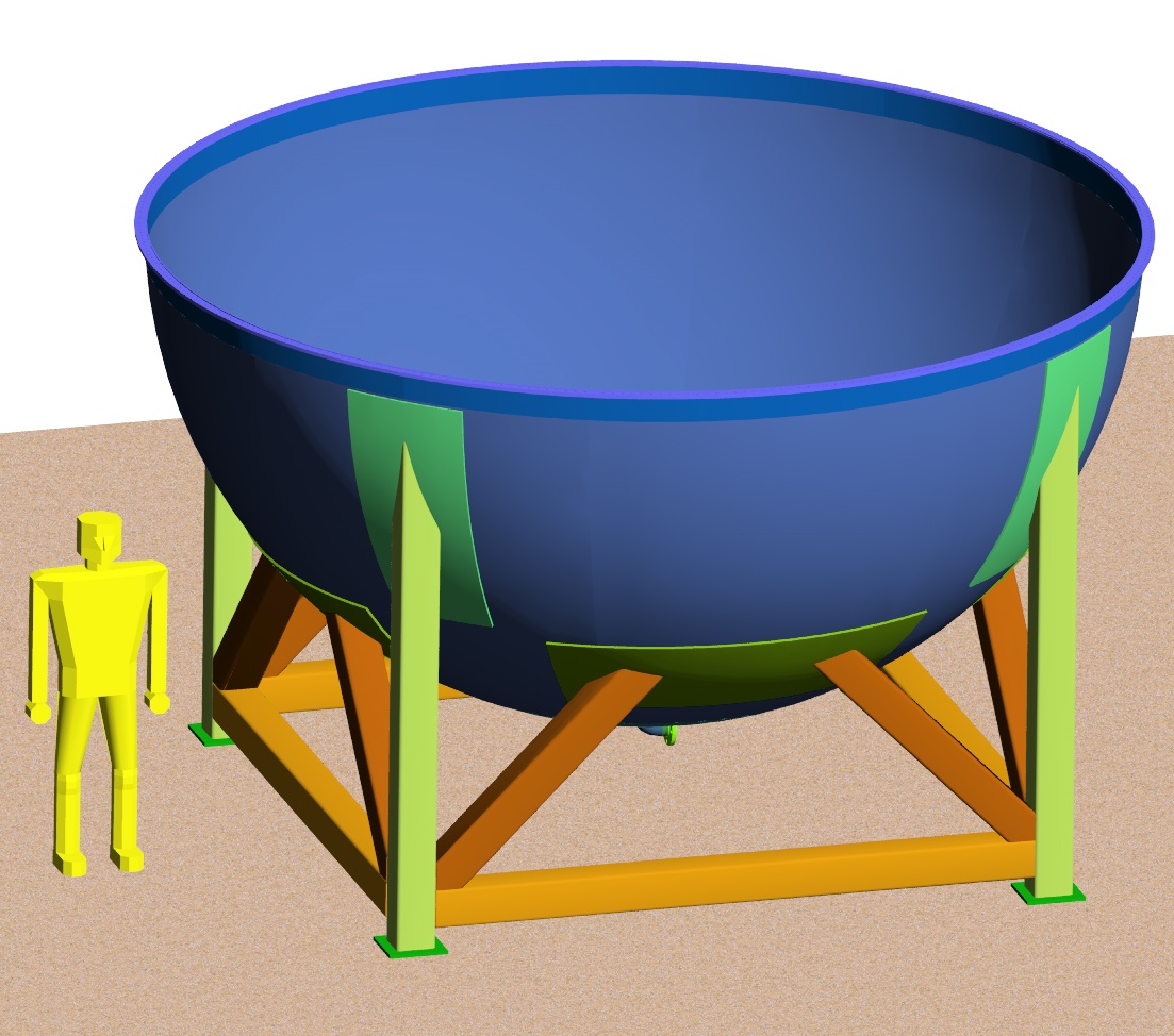
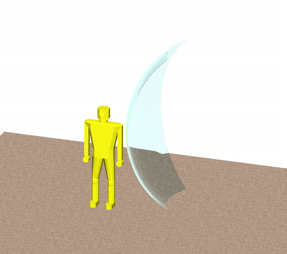
Constructing the lower half of the Steel Spherical Vessel
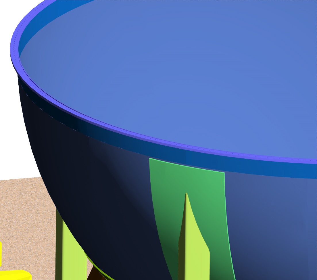
This style of construction of spherical storage tanks is referred to as "orange peel" because of the curved shape of the panels welded together to build up the sphere. The segmentation shown was driven by keeping part dimensions around 2 meters to fit through corridors at Krasnoyarsk. The welding sequence shown parallels that of the construction of the MiniBooNE sphere, but can be varied. Each orange peel is .25 inches thick, and weighs approximately 470 lbs.
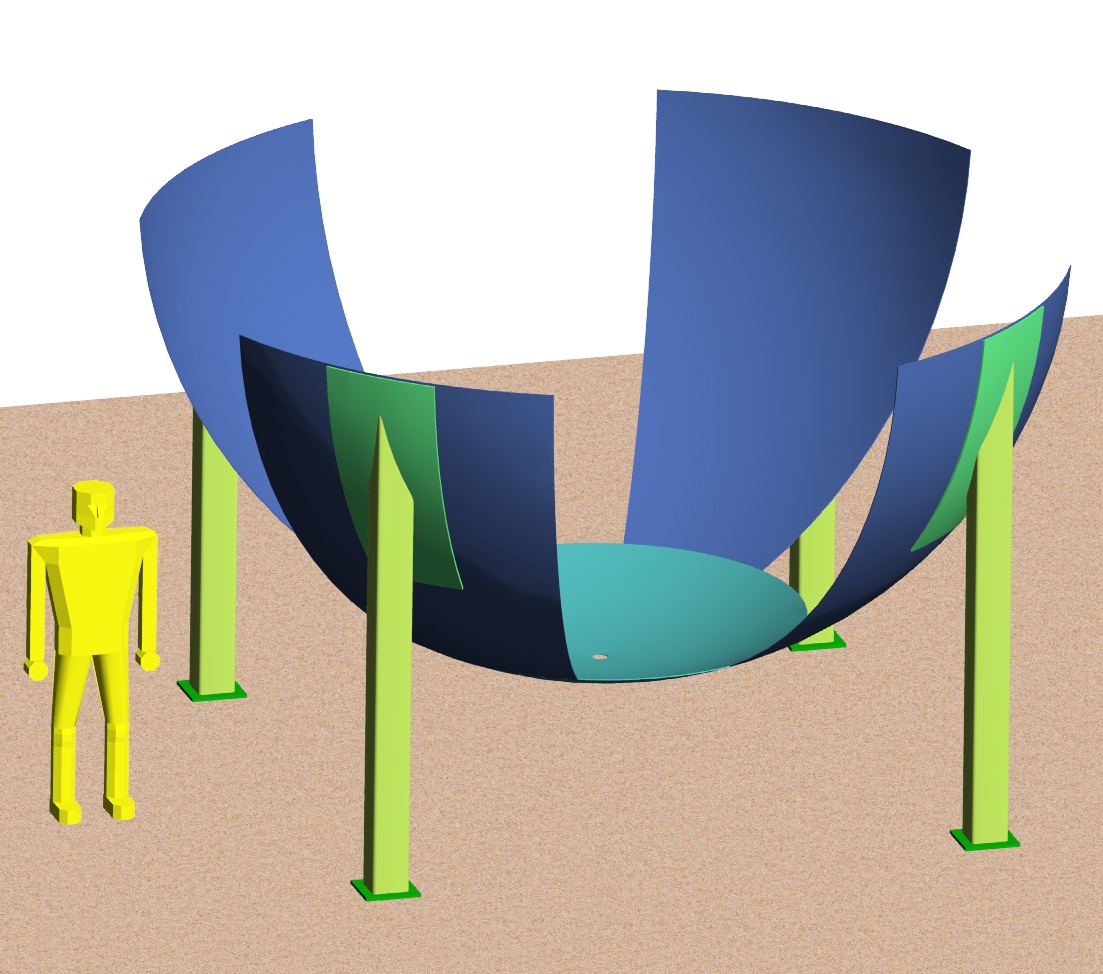
Once the half sphere is built up to just below the equator, the next sections to weld on are cylindrical to make welding the flange pieces on easier. The sphere is divided into 8 pieces in longitude. A drain port for the mineral oil surrounding the acrylic vessel is shown at the bottom of the half sphere. Control of liquid levels in both compartments of the detector is an important engineering challenge to be faced in future. No drain at the bottom of the acrylic sphere is imagined, so liquid will have to be removed from that vessel by suction pumping.
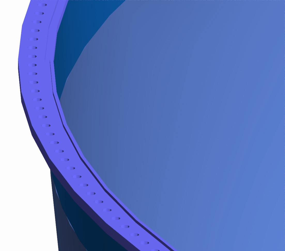
Welding the flange together, getting it flat enough, machining the o-ring groove, and 336 bolts holes are all manufacturing challenges that will have to be done inside the experimental hall at Krasnoyarsk. We will have to do some research on portable automatic mills that can be attached to the shell for these operations. What is not made clear in these pictures is that after assembly of the steel sphere, the steel must be painted on the inside with a flat black paint that will not dissolve in mineral oil.
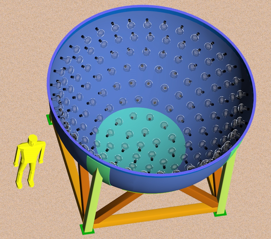
PMT Assembly into the Lower Half Steel Vessel
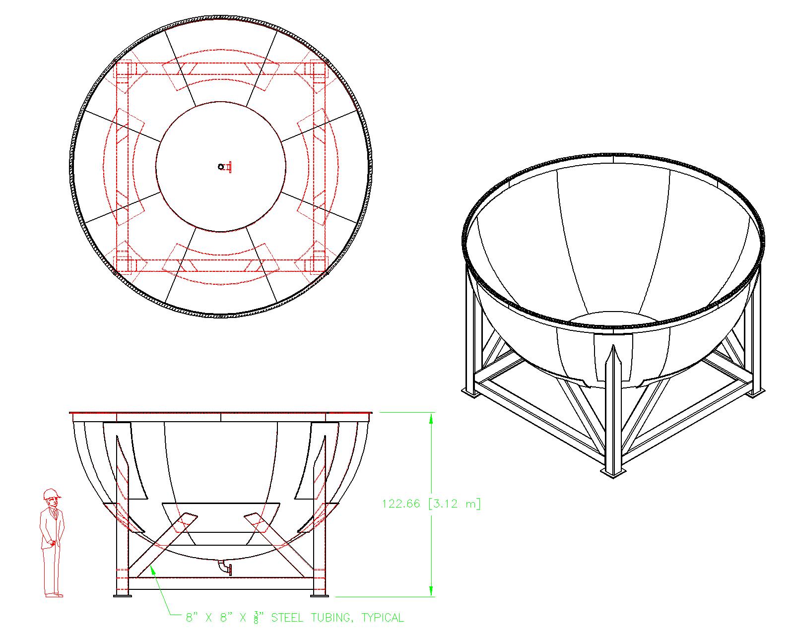
This picture shows the general layout of the 8" photomultiplier tubes arrayed around the inside of the spherical vessel. The support structure for the PMTs is not shown. Several options are being explored now depending on whether Winston cones would be a worthwhile addition to the PMTs. The order of assembly of the PMTs is not known yet. In MiniBooNE, there is a man-hole at the bottom of the spherical tank. Scaffolding was erected and PMTs were installed from top to bottom. As the PMTs filled the walls of the vessel, the scaffolding was disassembled and removed out the man-hole. A man-hole is an option for this vessel that is not shown. What may make more sense is to tip the half shell on its side and build scaffolding that allows access to the inside wall, but can be easily removed sideways. The technique used will depend on the ability to lift multi-ton chunks of the apparatus. The bottom half sphere and its support legs weigh 10,600 lbs as shown.
To make assembly of the upper and lower halves easier, the cables for the PMTs in the lower half might be routed through an oil-tight bulkhead port not shown somewhere on the lower half vessel.
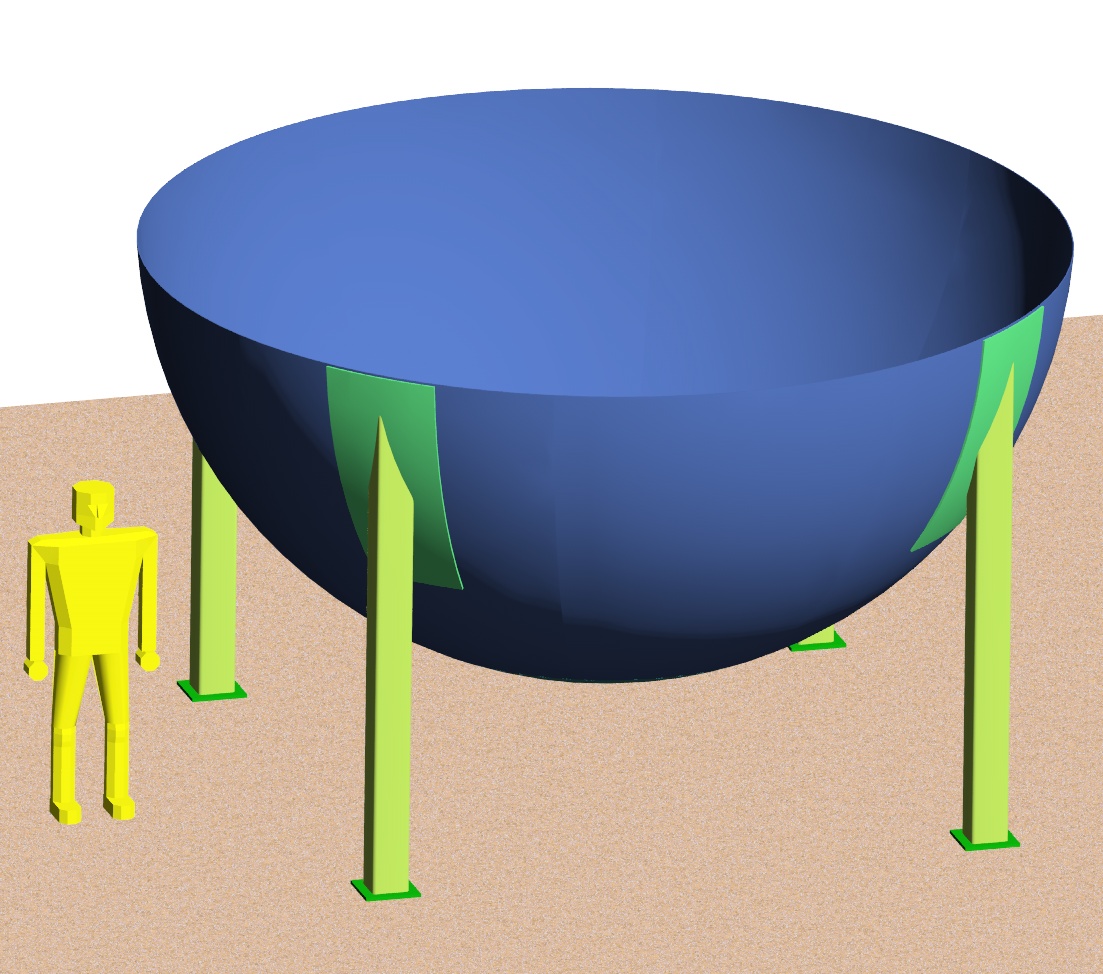
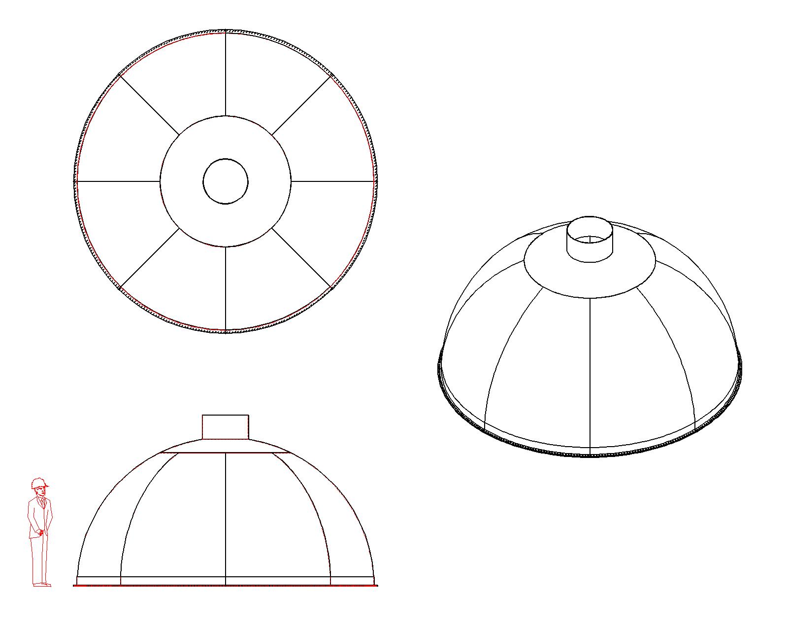
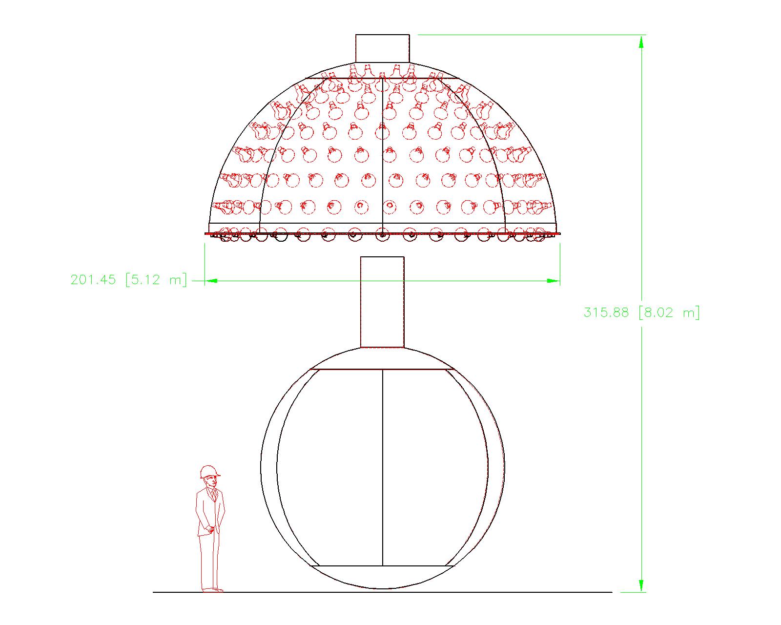
The Upper Half of the Steel Spherical Vessel
Construction of the upper half steel sphere proceeds in much the same way as for the lower. Temporary fixturing equivalent to the lower half's support structure may be needed to align the sections during welding. A significant difference between the top and bottom halves is the presence of the "chimney" on the top half. The chimney's features are not fully designed yet. No ports are shown for cable feed-throughs, no calibration instrumentation has been designed yet. The vessel must be kept purged with dry nitrogen to prevent aging of the oils and liquid scintillator in the acrylic vessel. Temperature regulation controls need to be considered. The weight of the upper half sphere is 4,660 lbs as shown.
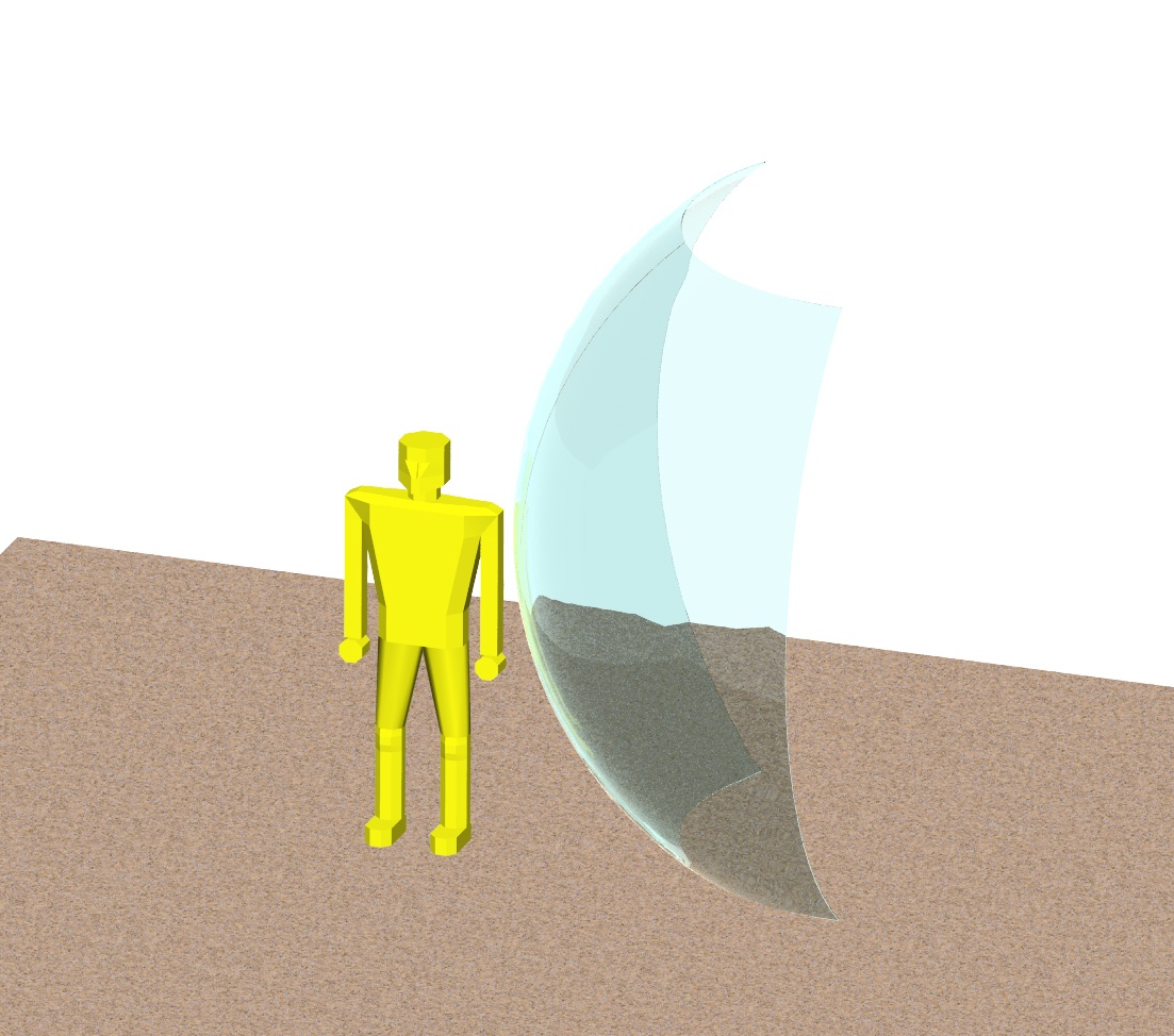
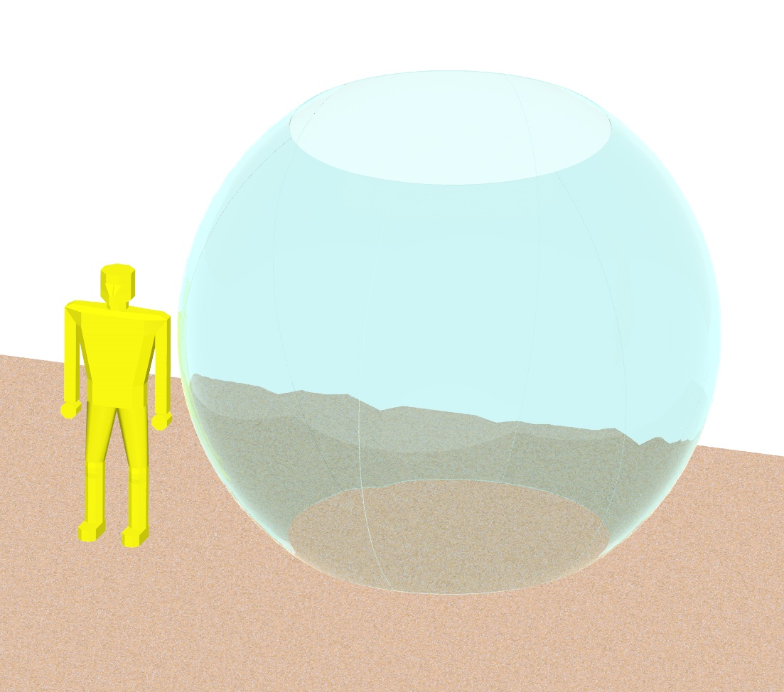
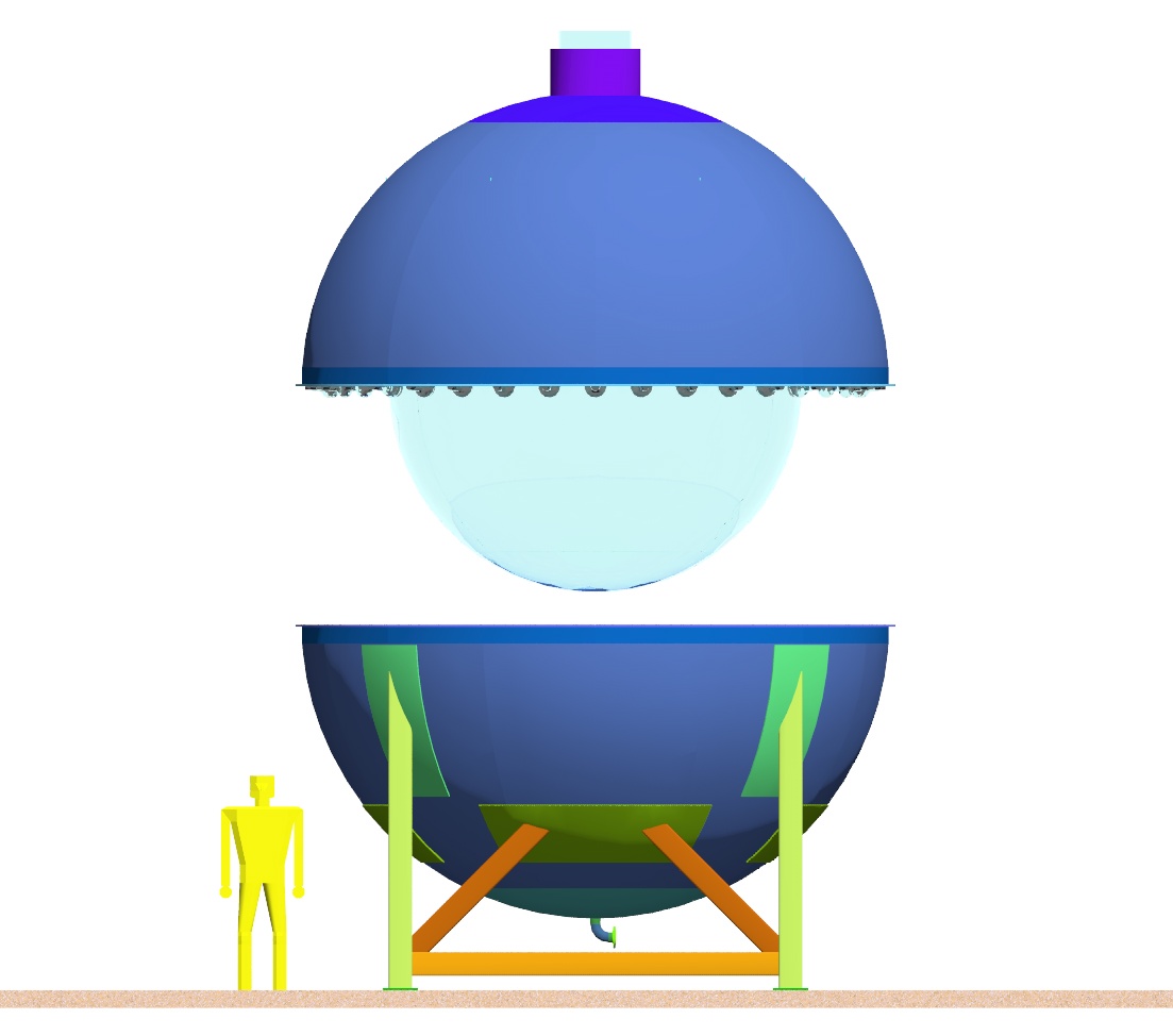
The construction of the Acrylic Sphere
The acrylic vessel in most of these renderings has been tinted blue to give some contrast to the white background. It will look like a clear aquarium vessel when the pieces are all bonded together and finished. Refer to the Powerpoint file below for details about the acrylic bonding process that would have to take place in the experimental hall. Simple calculations give an acceptable thickness for the acrylic of about a quarter inch. The SNO vessel was almost two inches thick. The simple calculations do not take into account the localized stresses from people walking around inside the vessel during the bonding and finishing of the joints. More analysis and consultation with the acrylic manufacturers is needed. Temporary fixturing of many different kinds will be necessary to support the vessel throughout the bonding process. The acrylic sphere shown weighs 680 lbs
Right click here to download a Powerpoint file about the Krasnoyarsk acrylic sphere. (.94M)
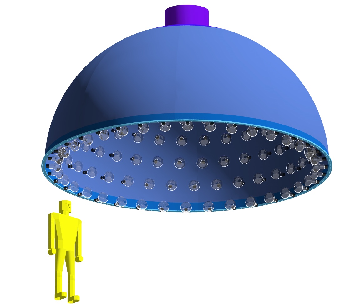
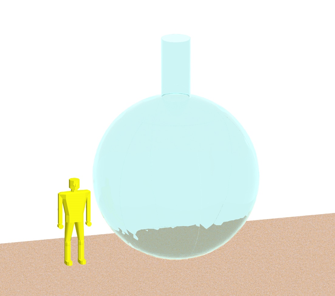
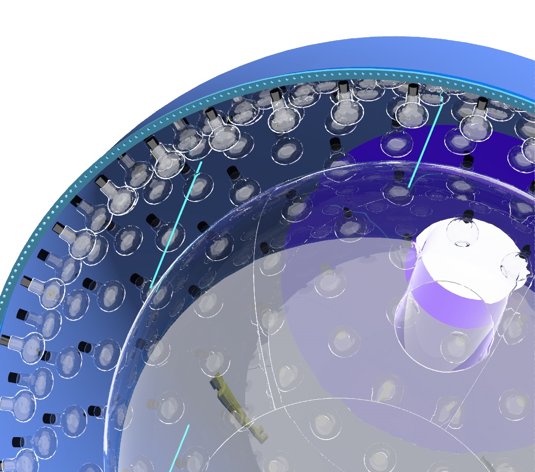
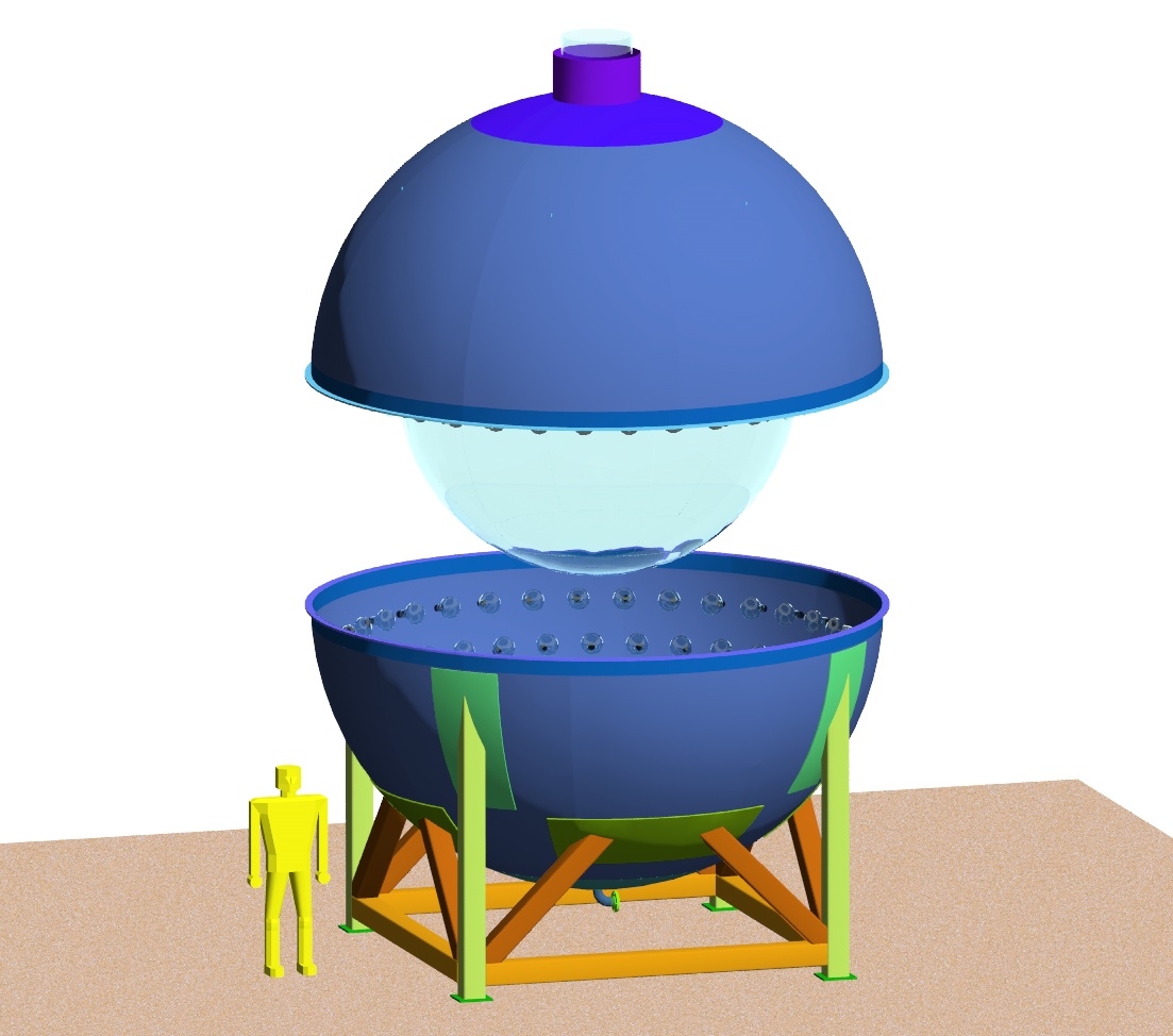
The Attachment of the Acrylic Sphere to the Upper Half Steel Vessel
The support system for the acrylic vessel is loosely based on the system developed for SNO. Tension cables of polymer support the vessel from the inside surface of the top half of the steel vessel. One interesting problem that is visible in the picture on the right of the first row is that any equally spaced array of six support ropes is likely to interfere with a PMT. The rope on the left side of this picture passes through a PMT. No attempt was made to optimize the support points because the PMT placement is not fixed yet. This is an assembly step that occupies about eight meters of height without including a building crane or any lifting fixtures. We will have to be clever to shoe-horn this assembly together inside the mountain.
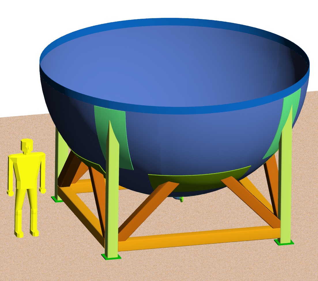
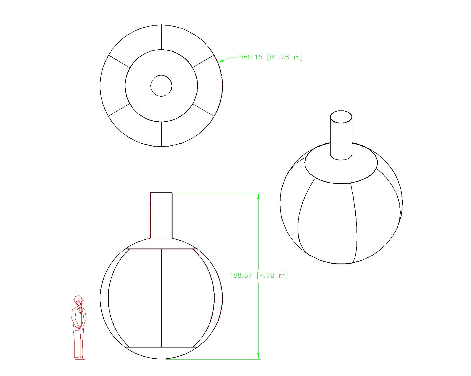
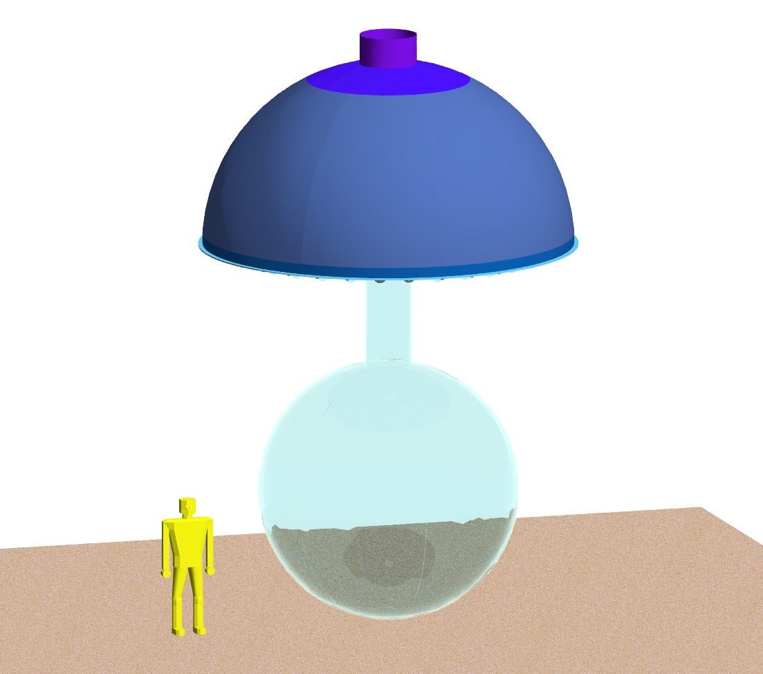
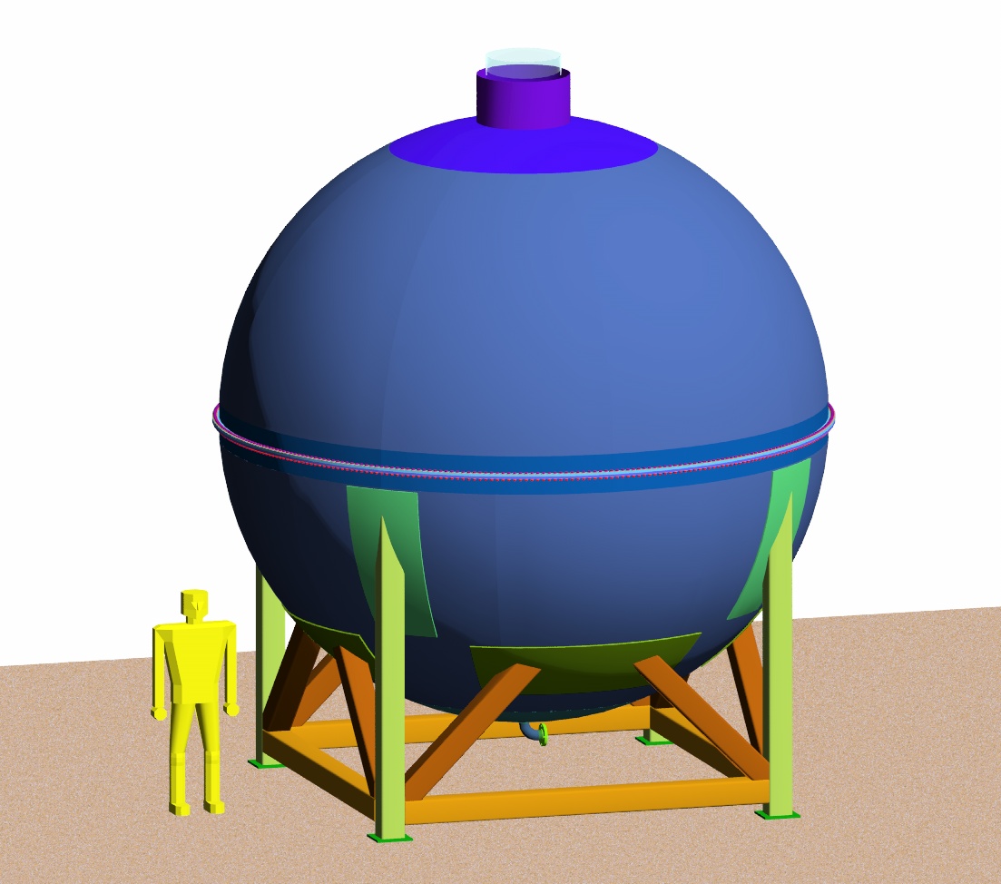
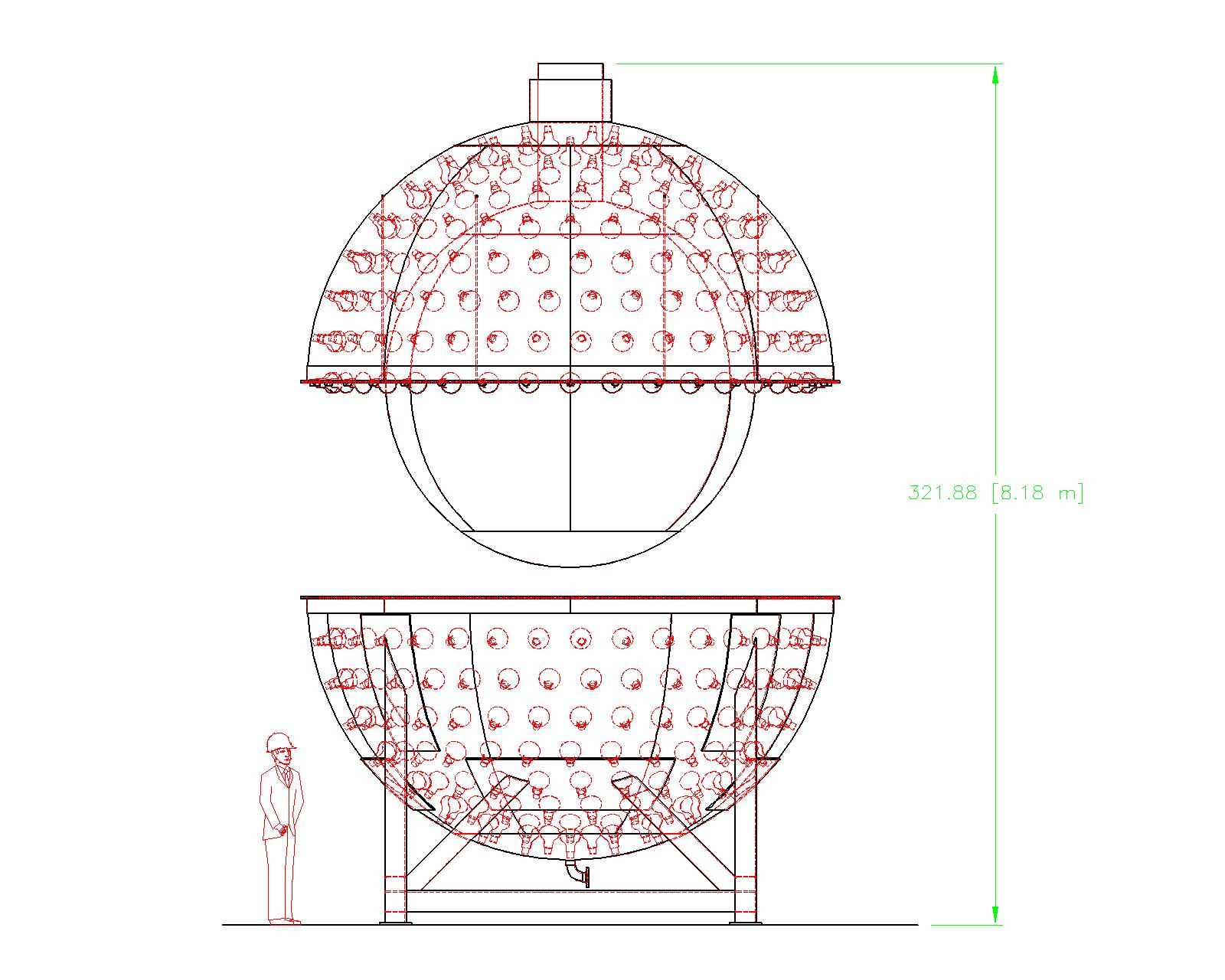
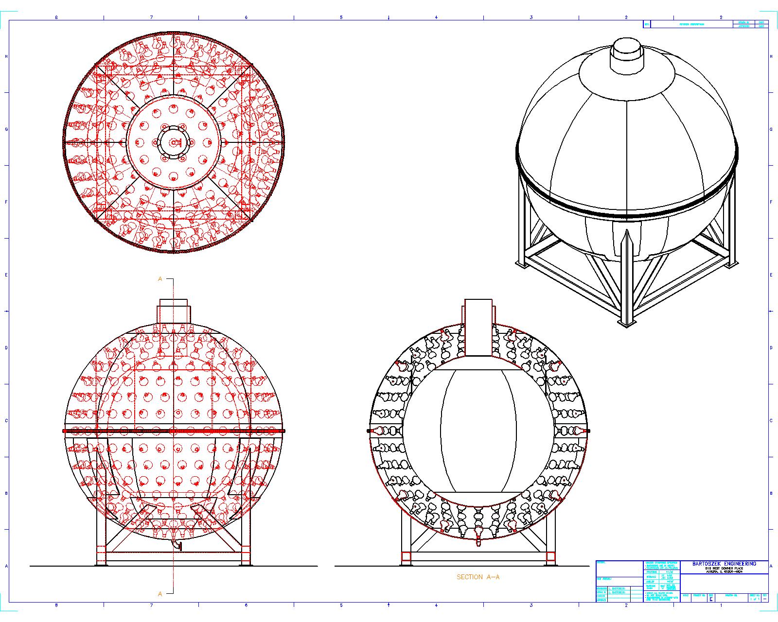
The Final Assembly of the Krasnoyarsk Detector
Final assembly also involves some height in the experimental hall to get the two halves together. Given the lack of detail in the chimney region, the heights shown should be taken as lower bounds. Once the detector is bolted together and leak checked, the fill process can start. The mineral oil in the PMT region must match the level in the acrylic sphere such that the acrylic sphere does not feel a significant buoyancy force. The liquid in the acrylic sphere is currently conceived to be a gadolinium-loaded liquid scintillator such as pseudo-cumene diluted with mineral oil or dodecane. Facilities for storing, purifying and pumping these liquids will be necessary in the experimental hall.
Link to an anonymous ftp site where AutoCAD Mechanical 2002 2D drawing files of the detector may be found
Back to the Bartoszek Engineering Projects Page
Back to the Bartoszek Engineering Home Page
|