Installation of the Ceramic Ring onto the Outer Conductor, 4/14/01We had a good day on Saturday getting the horn ready for surveying on Monday. All the brackets and fixtures worked, and we made a couple of improvements in the fixtures as we used them. The ceramic ring installation went without a hitch. Click on any of the thumbnails to get an enlarged view. You are welcome to download any of the images. If they are used for other than private viewing, credit to Bartoszek Engineering would be appreciated.
Stabilizing the Inner Conductor against sidesway, part 2
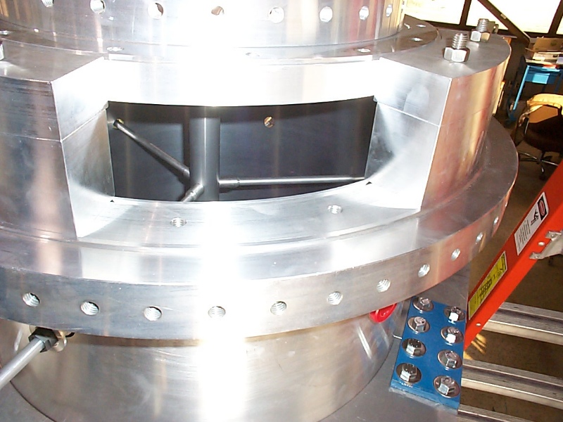
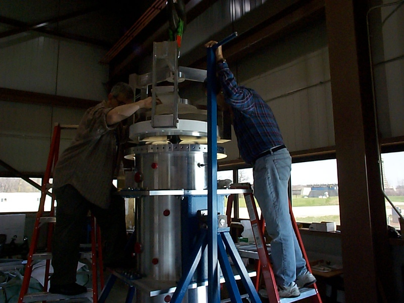
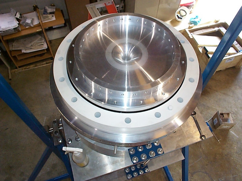
These pictures were taken after rotating the upstream end of the horn from the down position to the up position on the rotating fixture. We then installed the three rods that brace the IC from inside to allow the ceramic ring free passage down to the OC. This is a very tricky process as the Trantorques that hold the rods in place in the OC water ports tend to cause the rods to back out as they are tightened. The rods must be gently tapped into place as the Trantorques are tightened (without dinging the inner conductor). After the rods are set the outer brackets that protected the IC during rotation are removed.
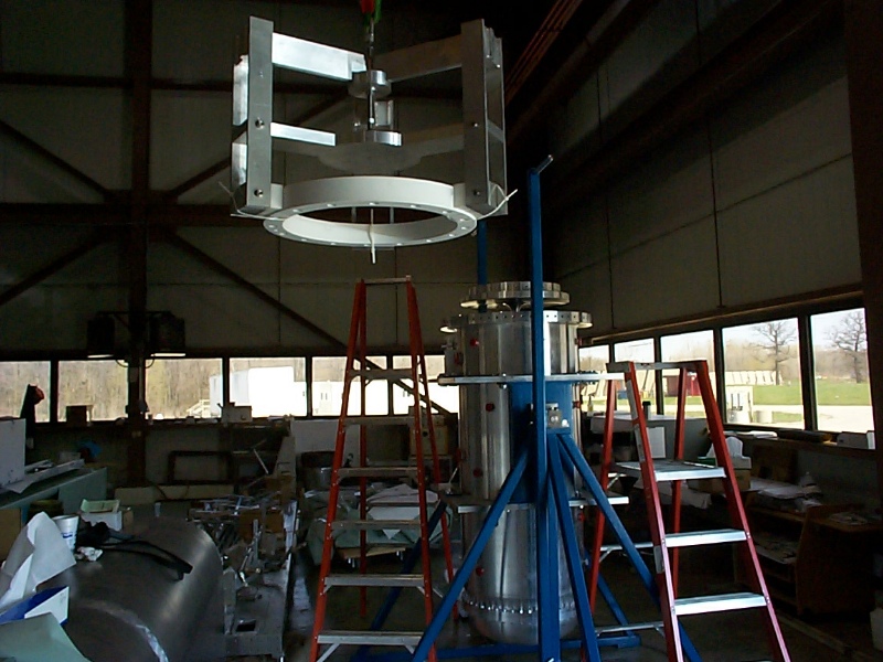
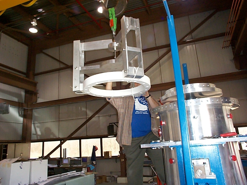
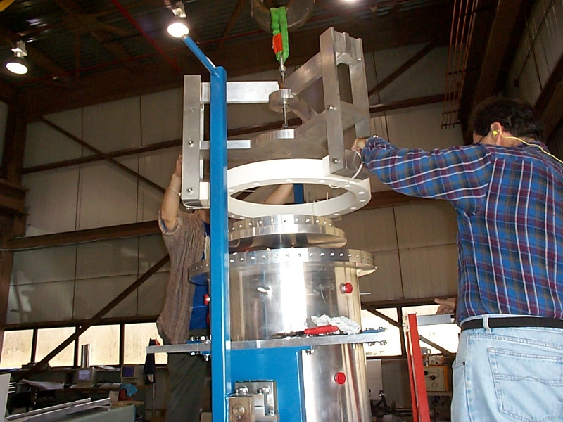
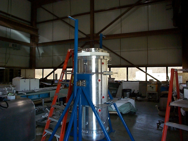
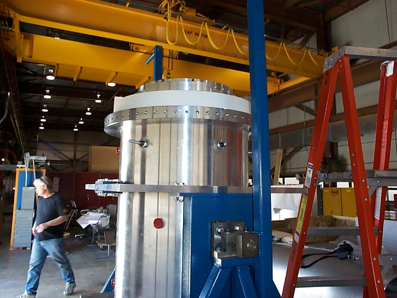
The flight of the Ceramic Ring
The main problem with the ceramic ring lifting fixture is the tendency of the stainless cone that drives the pivot arms to get stuck on the 3/4-10 threaded rod. We tried to wrap the threaded rod with kapton tape, but that really didn't work. For this fixture to work totally painlessly the 3/4-10 rod would have to be redesigned so that there were no threads inside the cone's range of motion. It would be a relatively expensive modification to a fixture that we only use a couple of times, so I don't think it would be worth doing at this point. A few raps with a hammer was enough to get it to unjam.
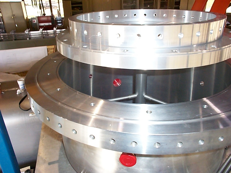
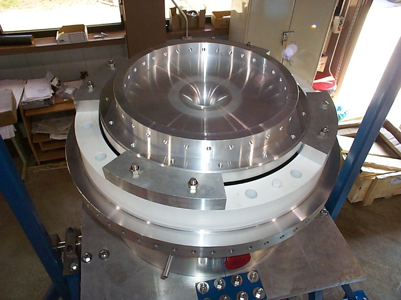
Assembling the second set of brackets to hold the Ceramic Ring during rotation
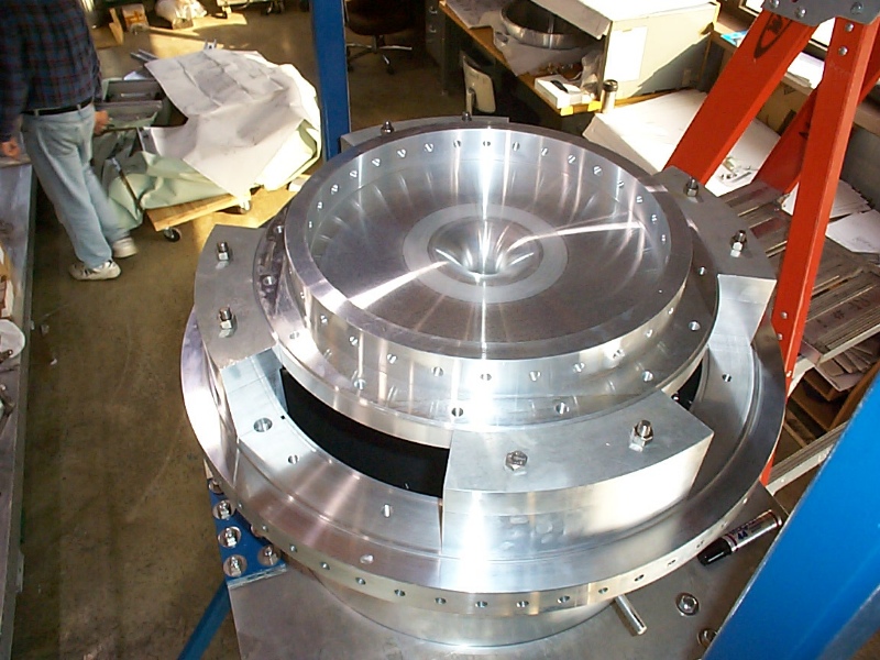
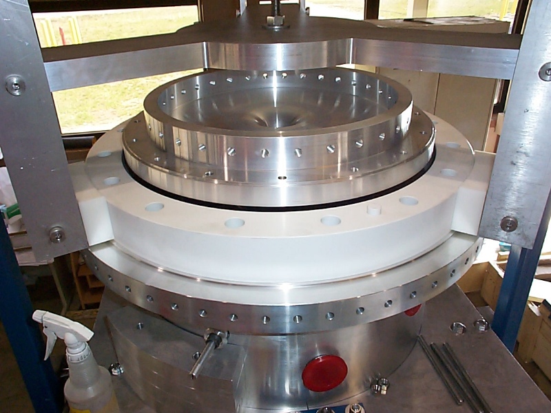
One of the things we learned during the test fitting of the horn support on the horn box was that aluminum rubbing against ceramic leaves a metal smear on the ceramic. Around the 1/2-13 rods that hold these brackets on are aluminum cylinders, which are hidden under the brackets in a counterbore. It would not be good to smear a conductive trail of aluminum on the inside of the holes of the ceramic ring (which sees about a 4kV potential difference), so one of the modifications we made was to wrap kapton tape around those cylinders so that aluminum would not touch the ceramic ring inside the holes. This worked like a charm. We are ready for survey on the bolt pattern alignment and the final pocket depth on the upstream flange. Back to the MiniBooNE Horn Main Menu Back to the Bartoszek Engineering Home Page |