|
The PHENIX RPCs at Brookhaven National Laboratory
Bartoszek Engineering worked with Matthias Grosse Perdekamp of the University of Illinois and many others from Brookhaven National Laboratory on the PHENIX RPC upgrade at the RHIC accelerator at Brookhaven National Laboratory (BNL). BE's role was to design the Resistive Plate Chamber (RPC) containers and figure out how to install them in the very tight spaces left in the PHENIX experiment. We were initially going to design six different detectors, RPC1, 2 and 3 for both the north and south sides of PHENIX. RPC2 turned out to be impossible to install on either the north or south sides, so it was abandoned. RPC3 exists in the space between the accelerator tunnel and the detector enclosure. The space was approximately 4 stories tall, 4 stories wide, and only 5 inches thick in the beam direction. RPC3 was installed in the end of 2009. RPC1 was installed in 2011 by Don Lynch and his very capable crew of technicians. BE did the conceptual design of RPC1 supports, but Don did the final design as the absorber behind RPC1 changed dramatically.
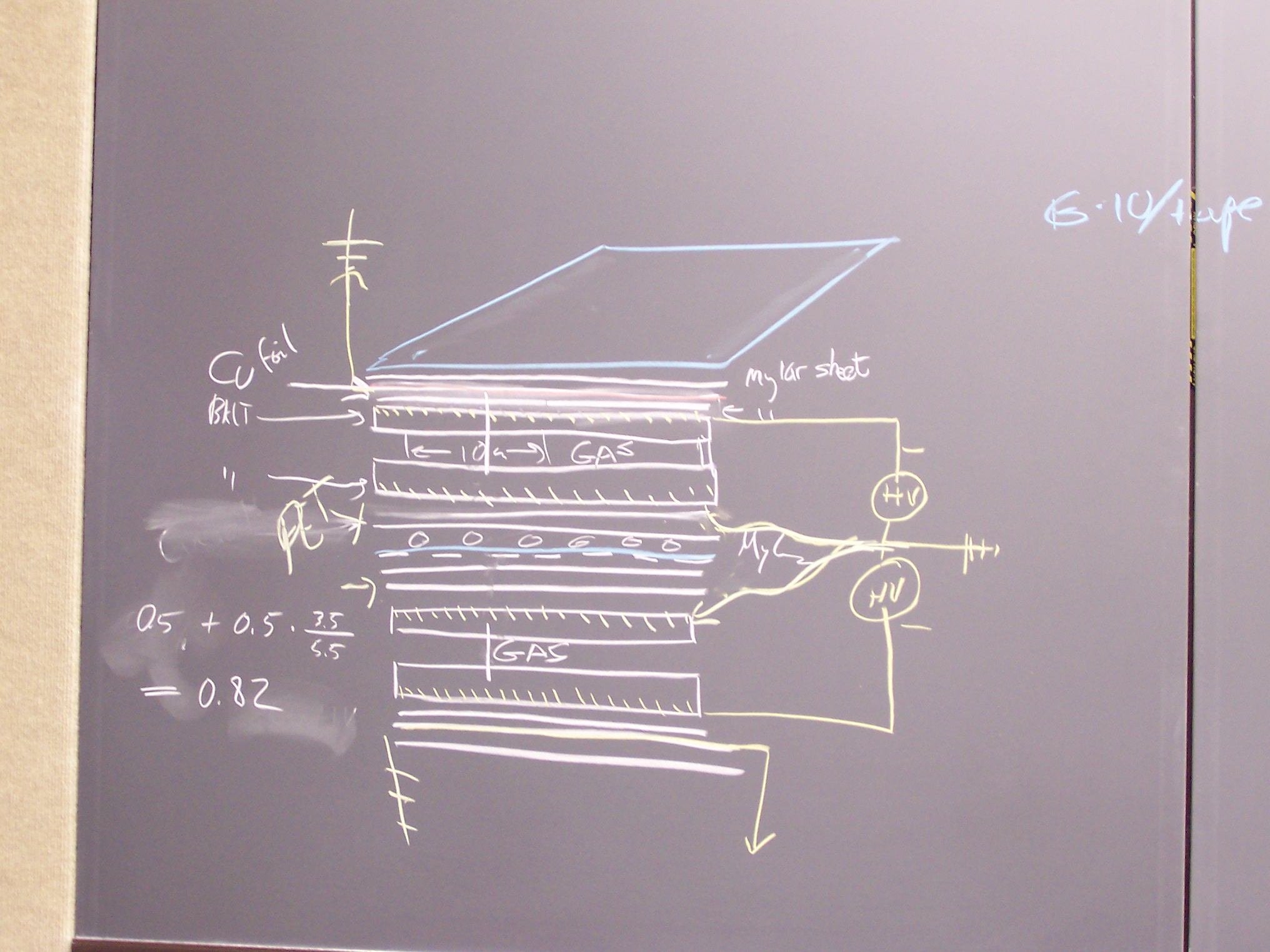
RPCs were developed for the CMS detector at the LHC on a massive industrial scale. PHENIX is using many of the same institutions in Italy, Korea and China that know the secrets of preparing the detectors. RPCs are "interesting" things that use high voltage across either glass or phenolic plates, a custom tailored gas mixture and readout strips. Radiation passing through the plate causes charge to bleed through the insulators creating a signal that can be used to measure the location of the particle that passed through the detector. The following link is to a pdf status report by a group at CMS on the LHC that is a pretty good description of the way RPCs work and how they are used in the LHC and elsewhere. I also have an early ppt given by Byungsik Hong of Korea University here that describes PHENIX RPC manufacturing and use. Click on any of the thumbnails to get an enlarged view. You are welcome to download any of the images. If they are used for other than private viewing, credit to the PHENIX collaboration and Bartoszek Engineering would be appreciated.
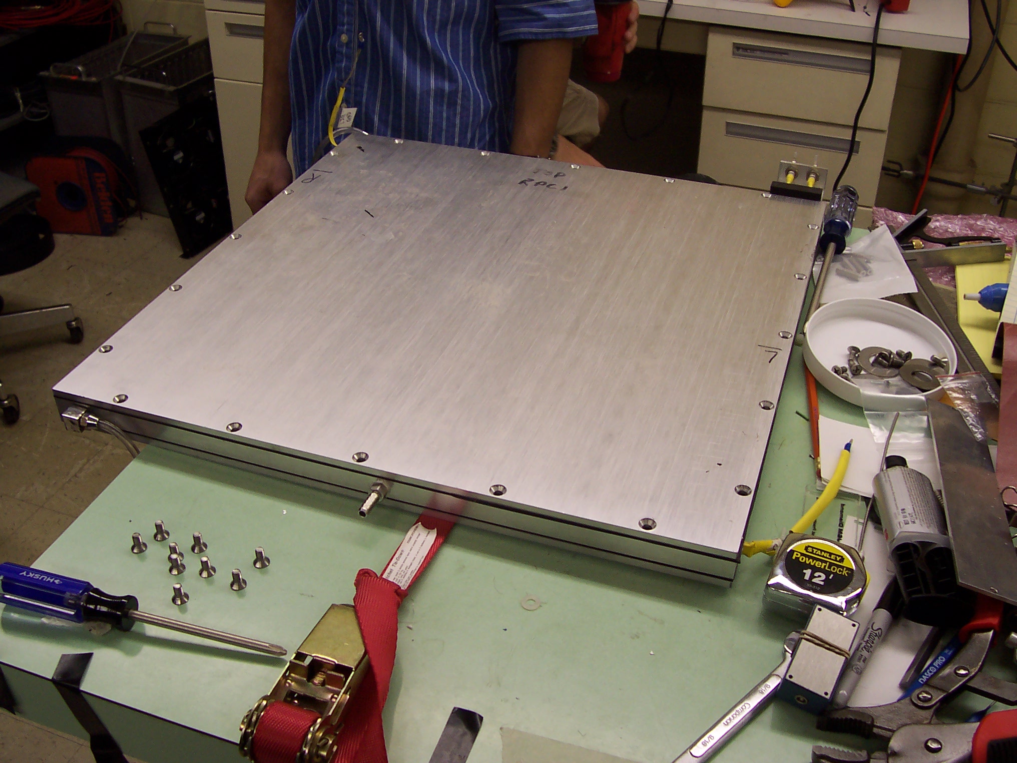
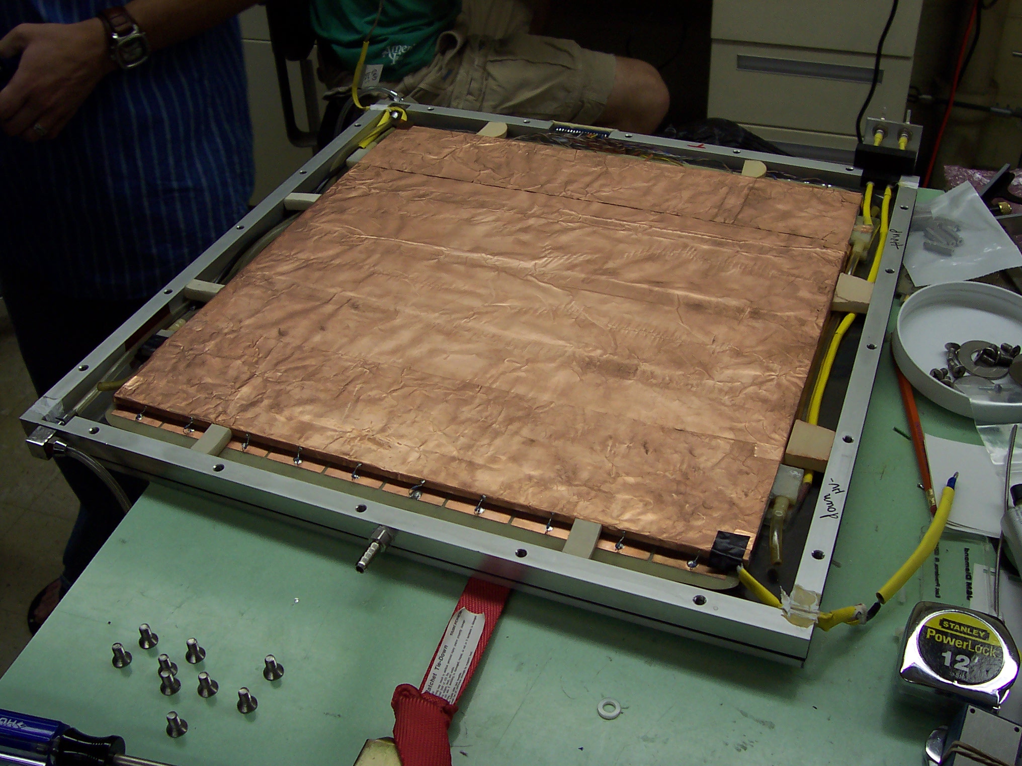
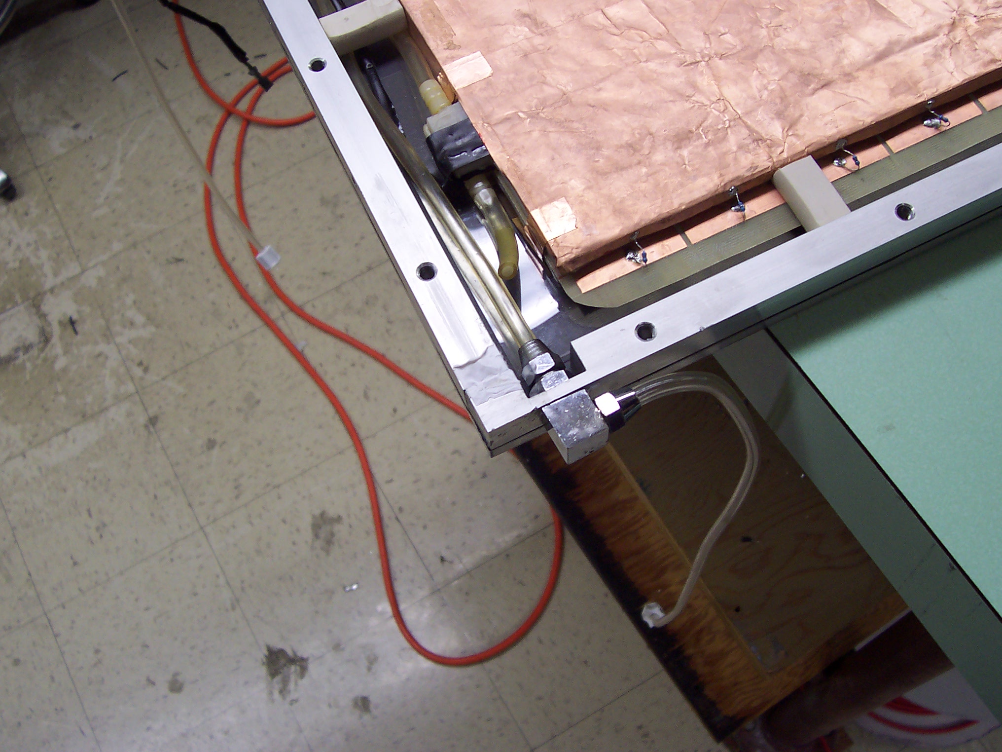
These pictures show the test RPC in the lab at UIUC (and the blackboard where people described for me how they worked).
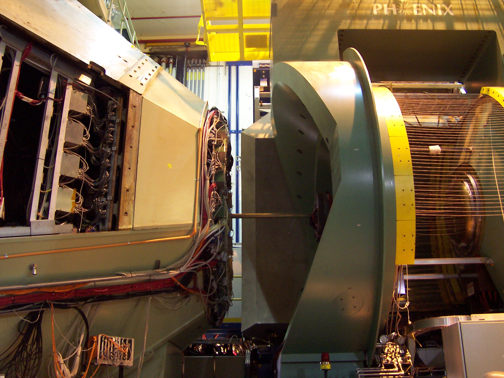
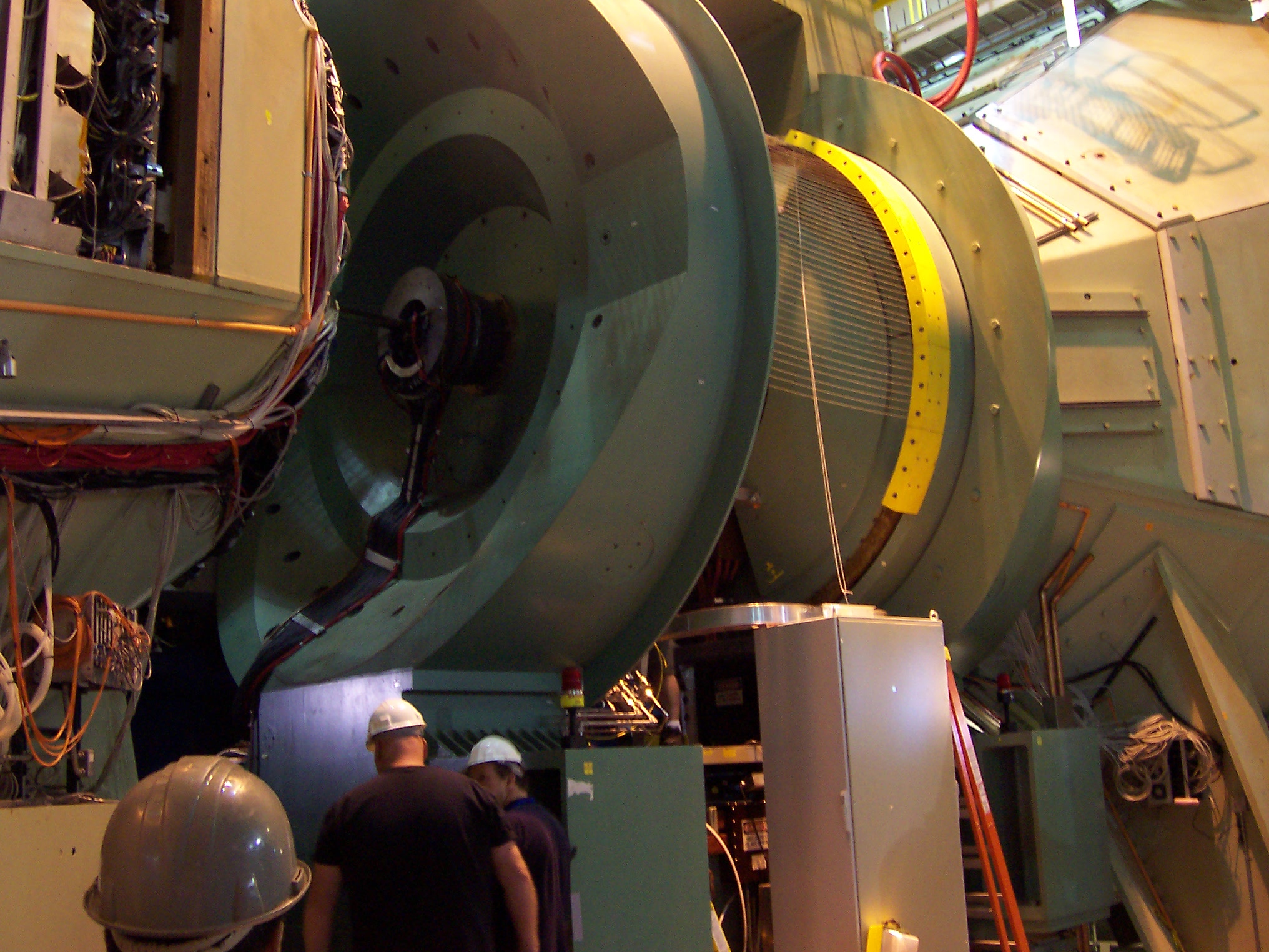
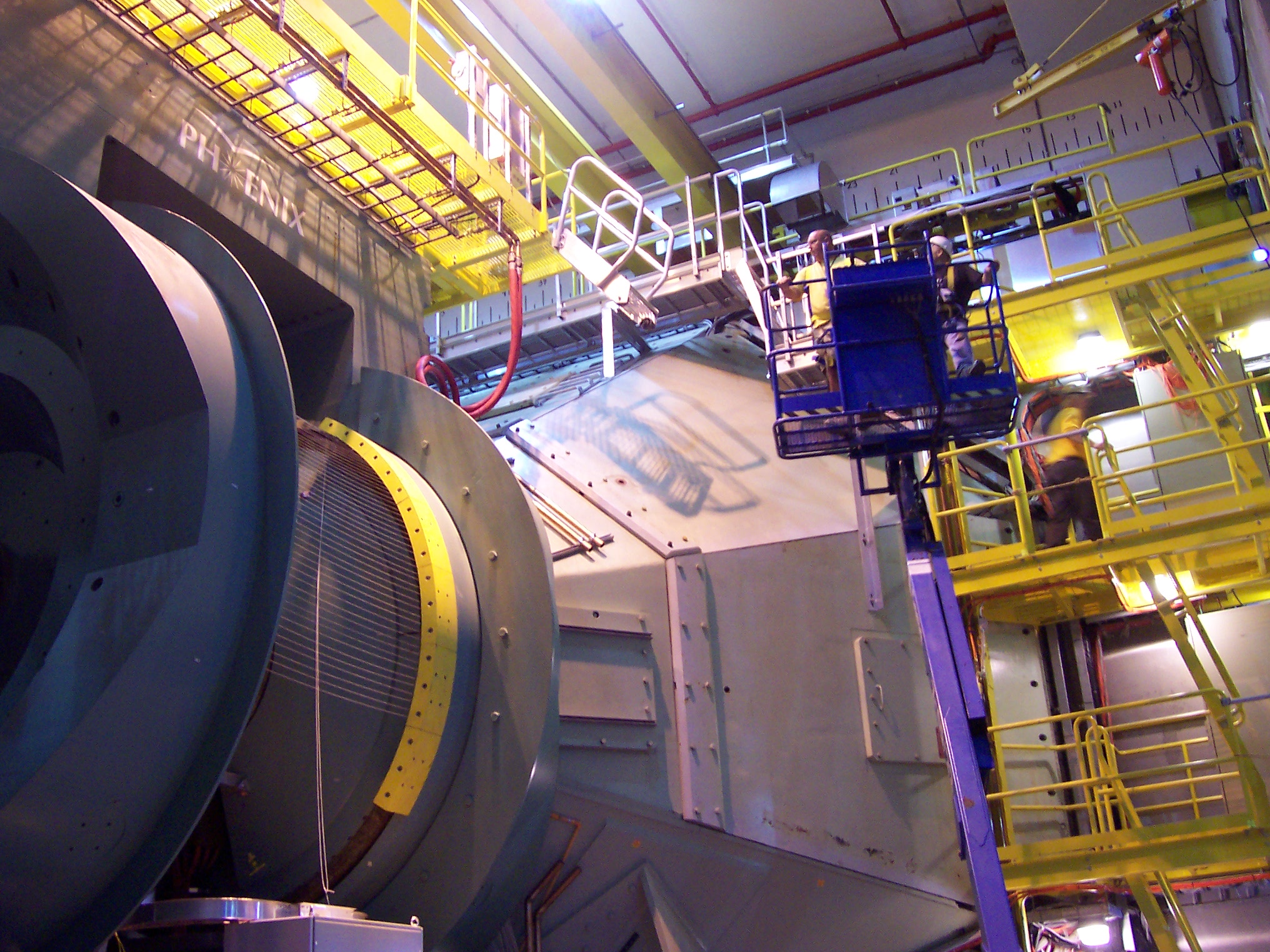
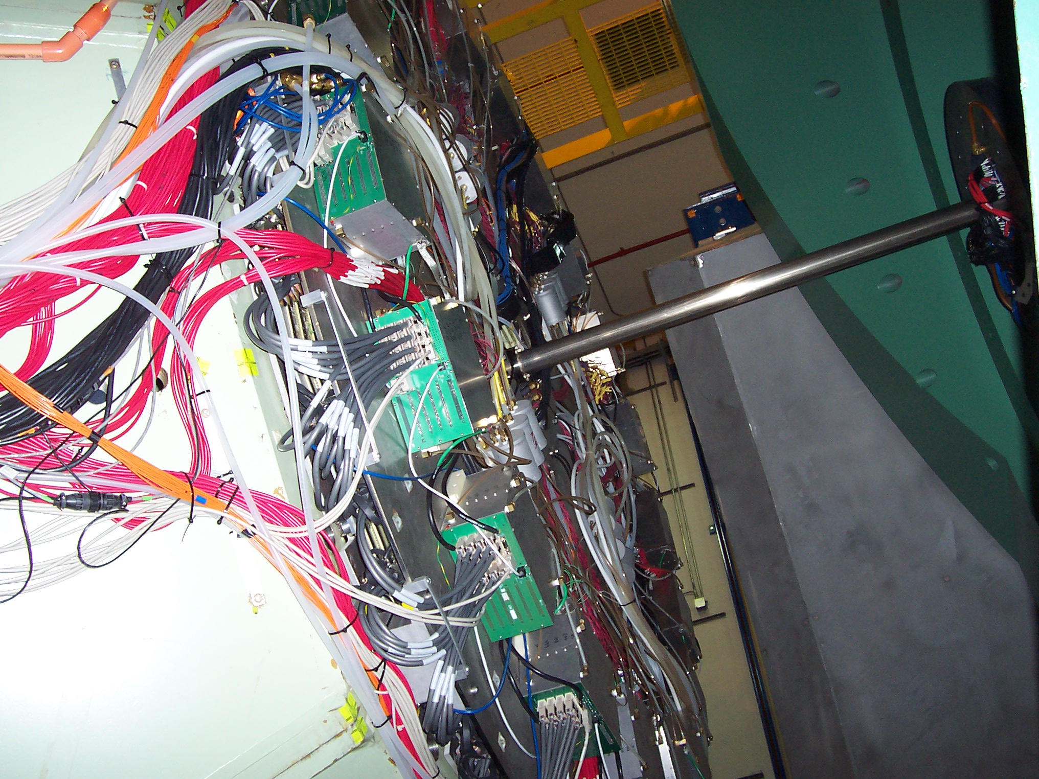
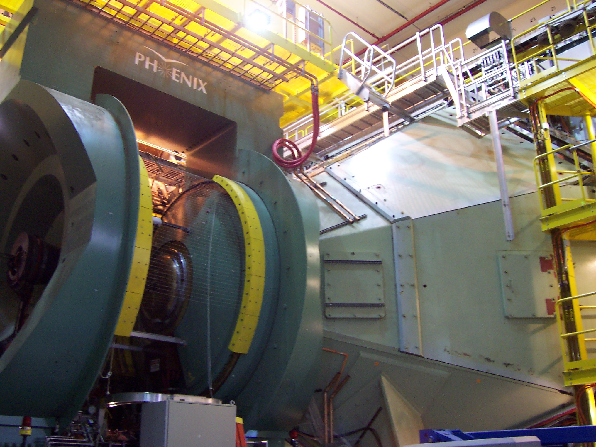
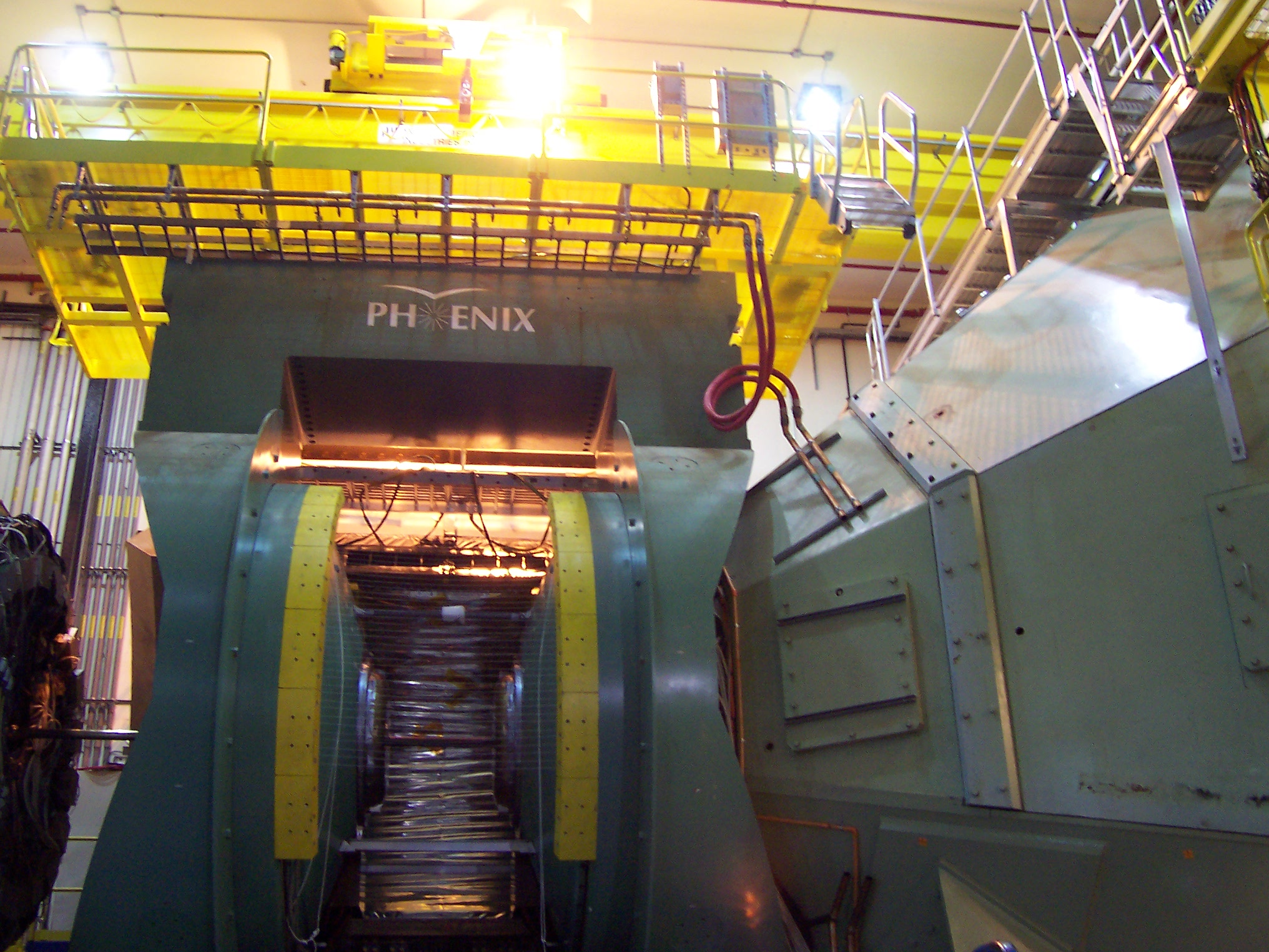
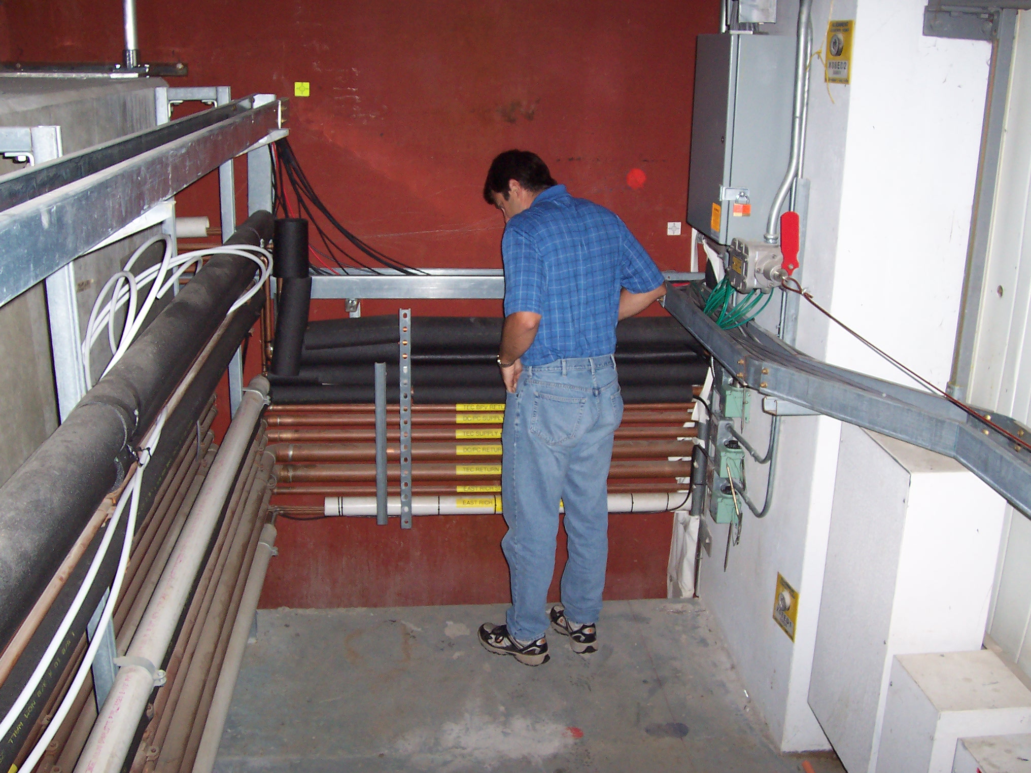
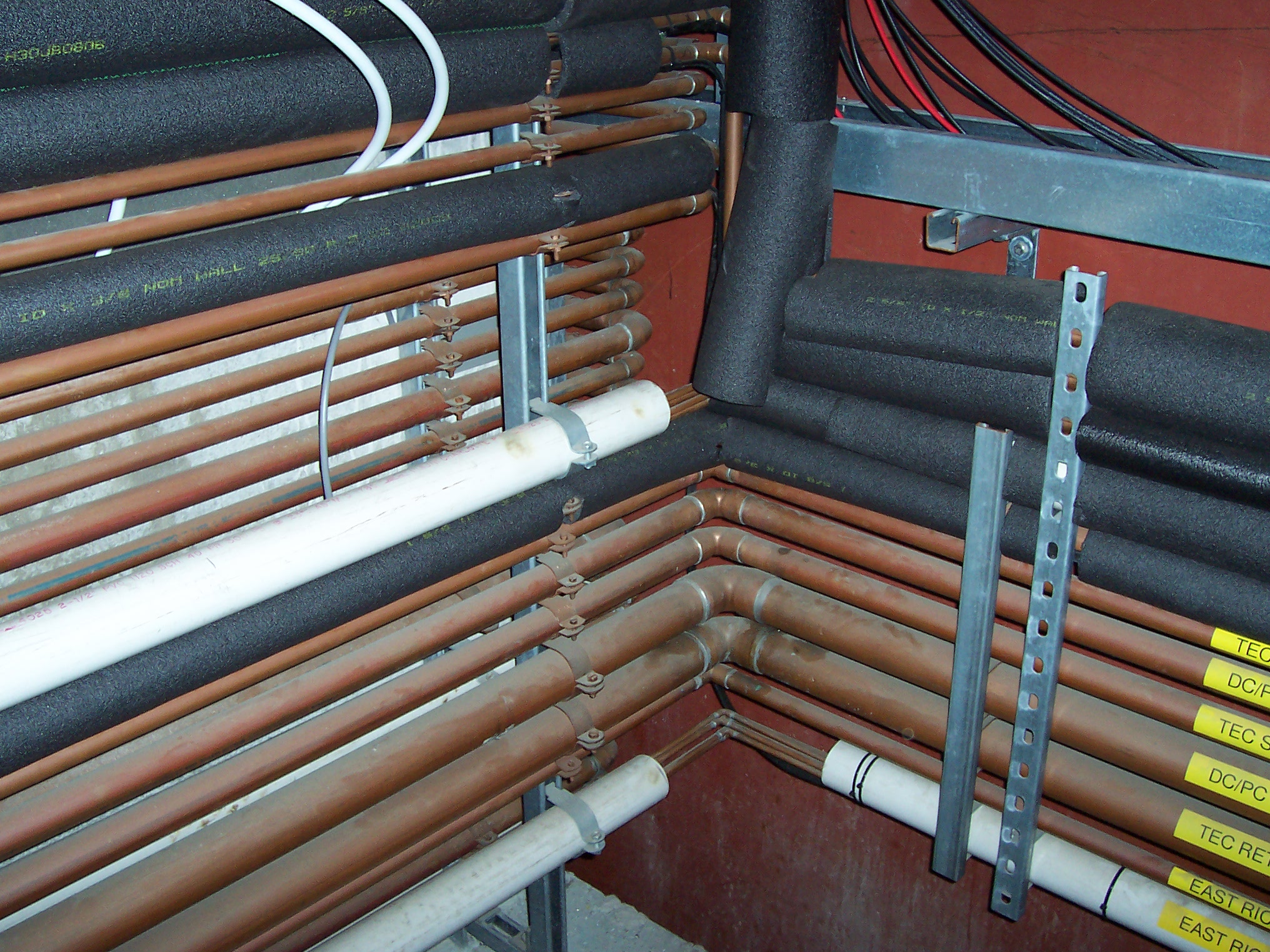
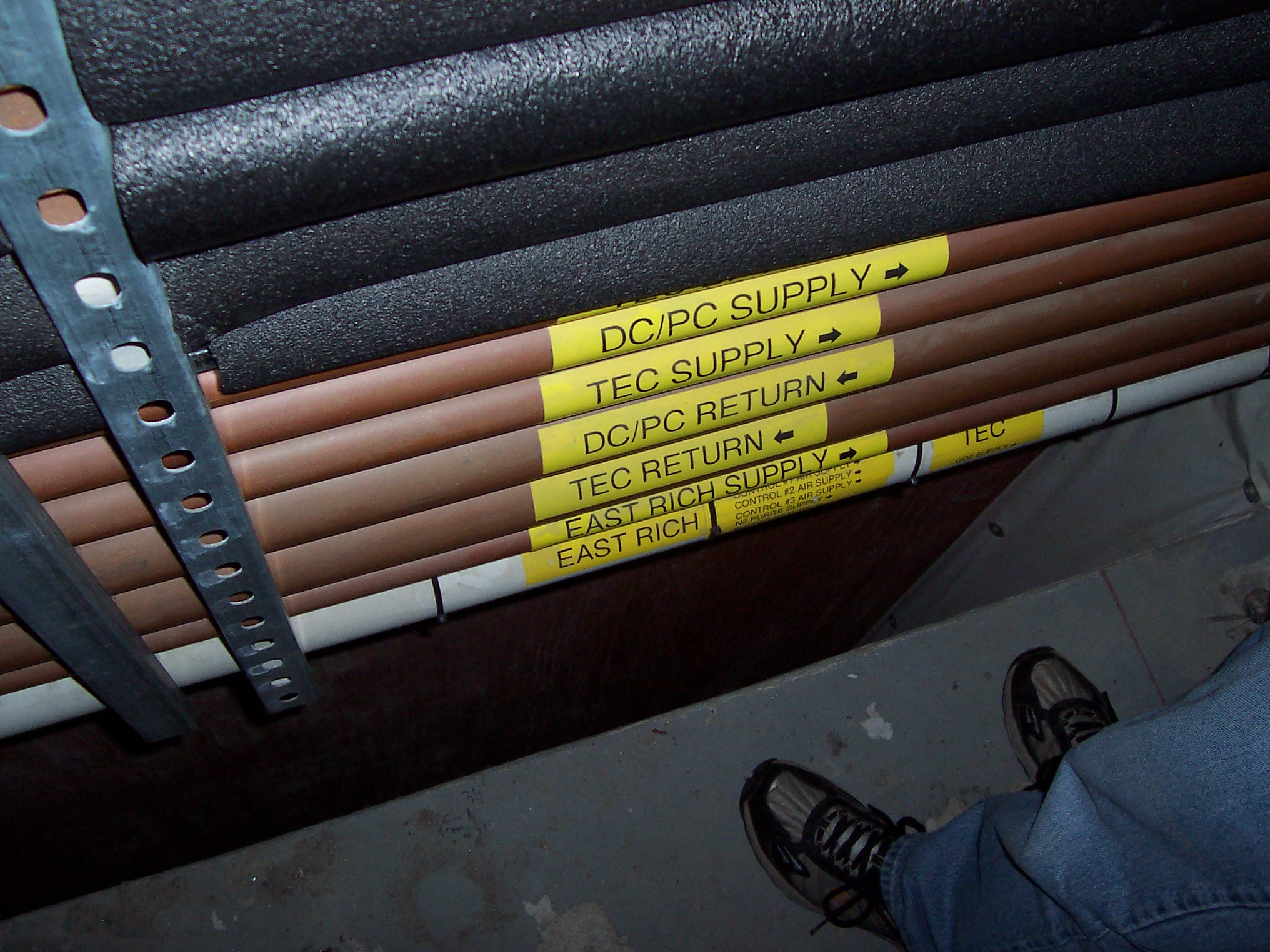
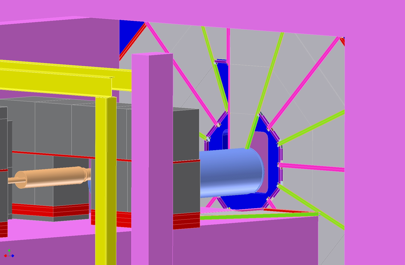
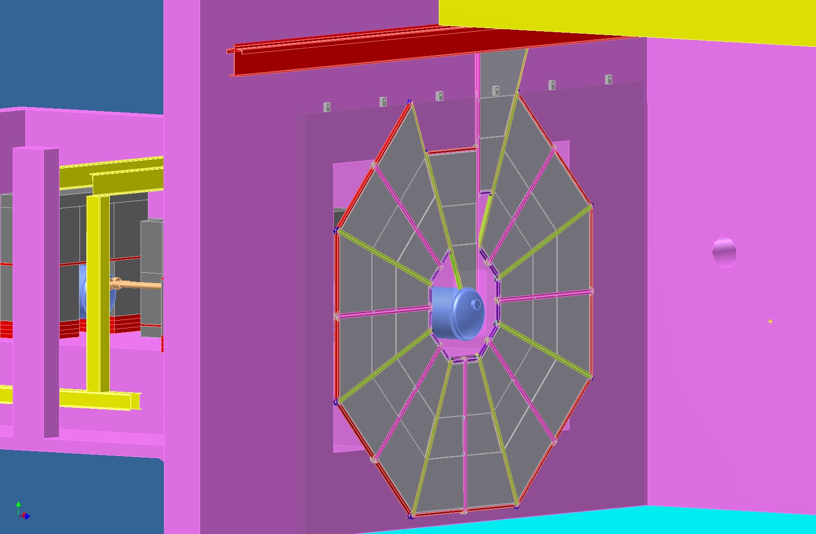
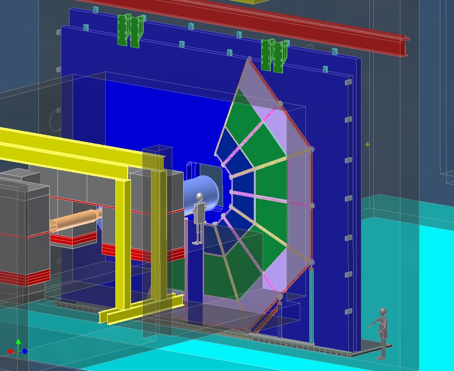
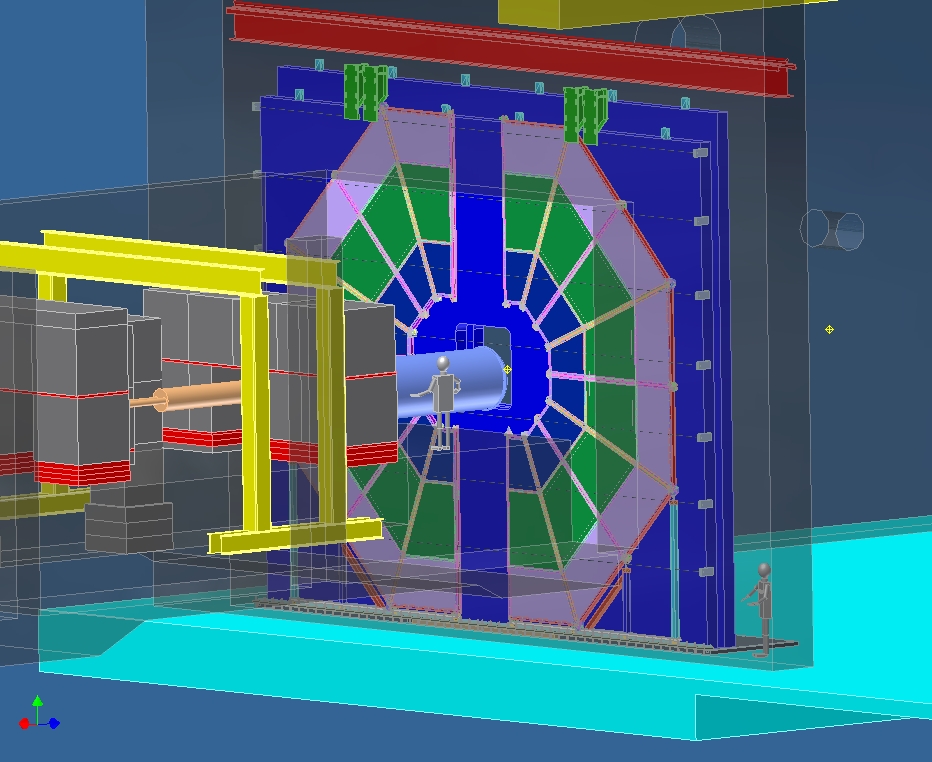
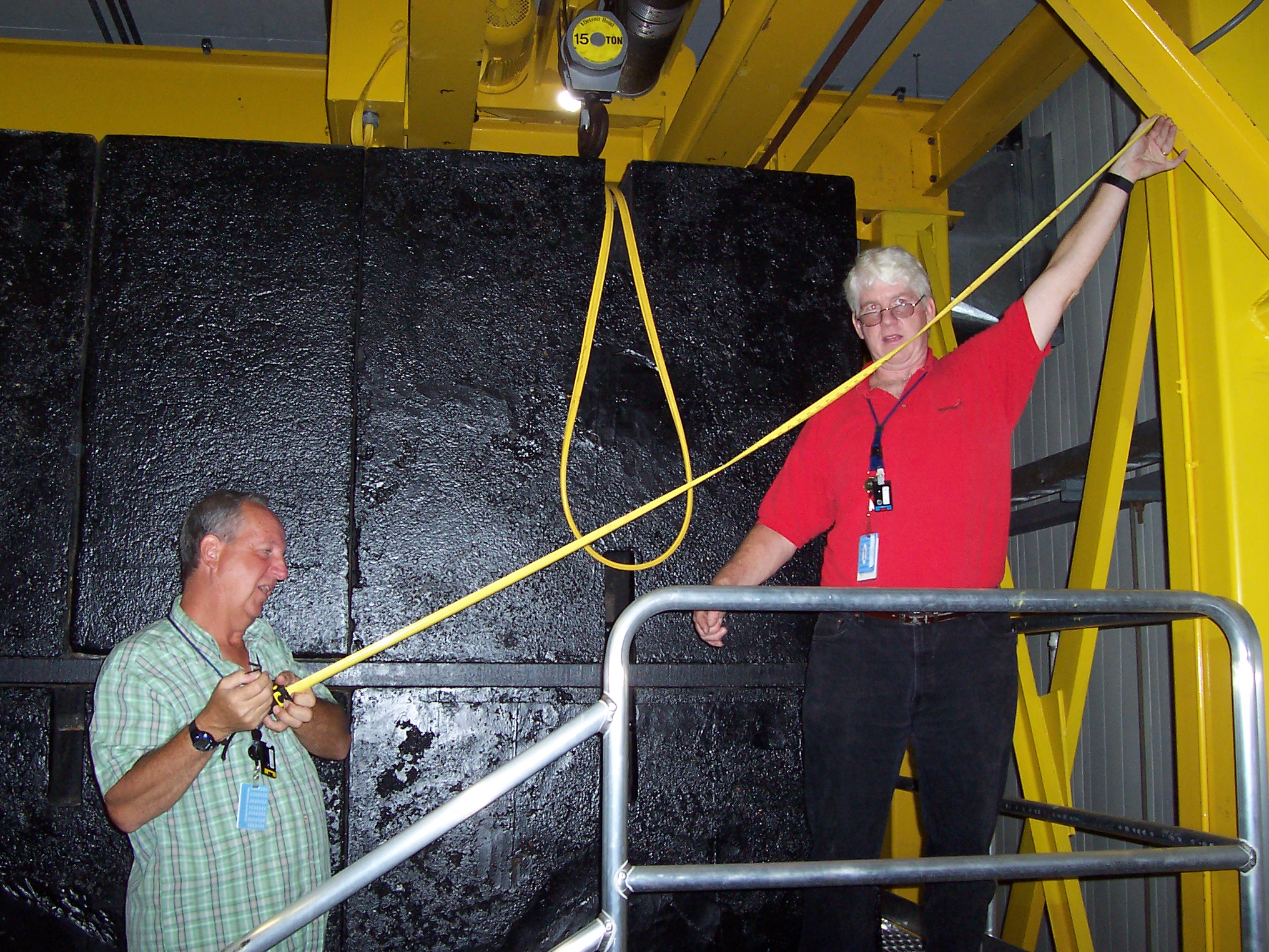
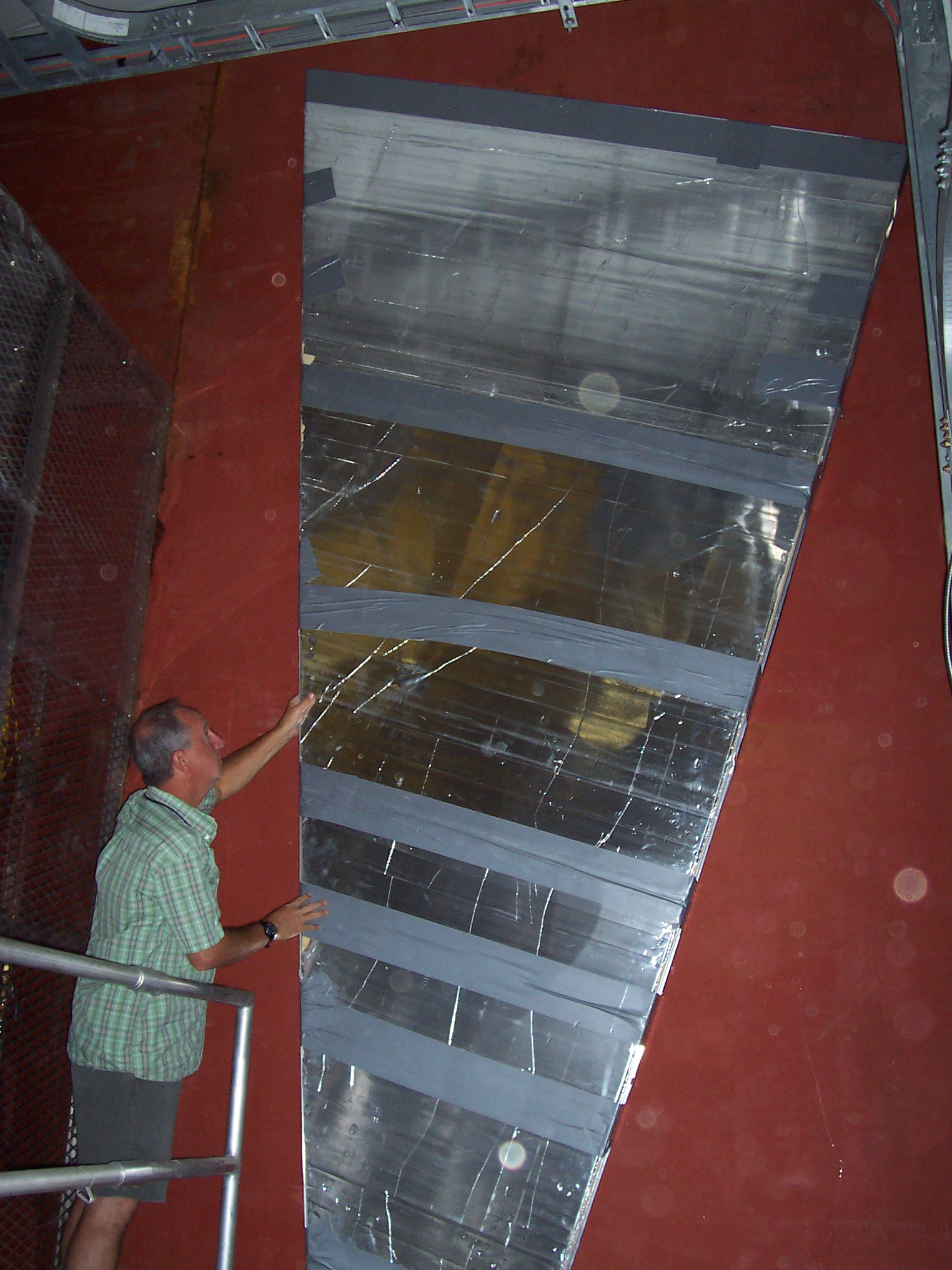
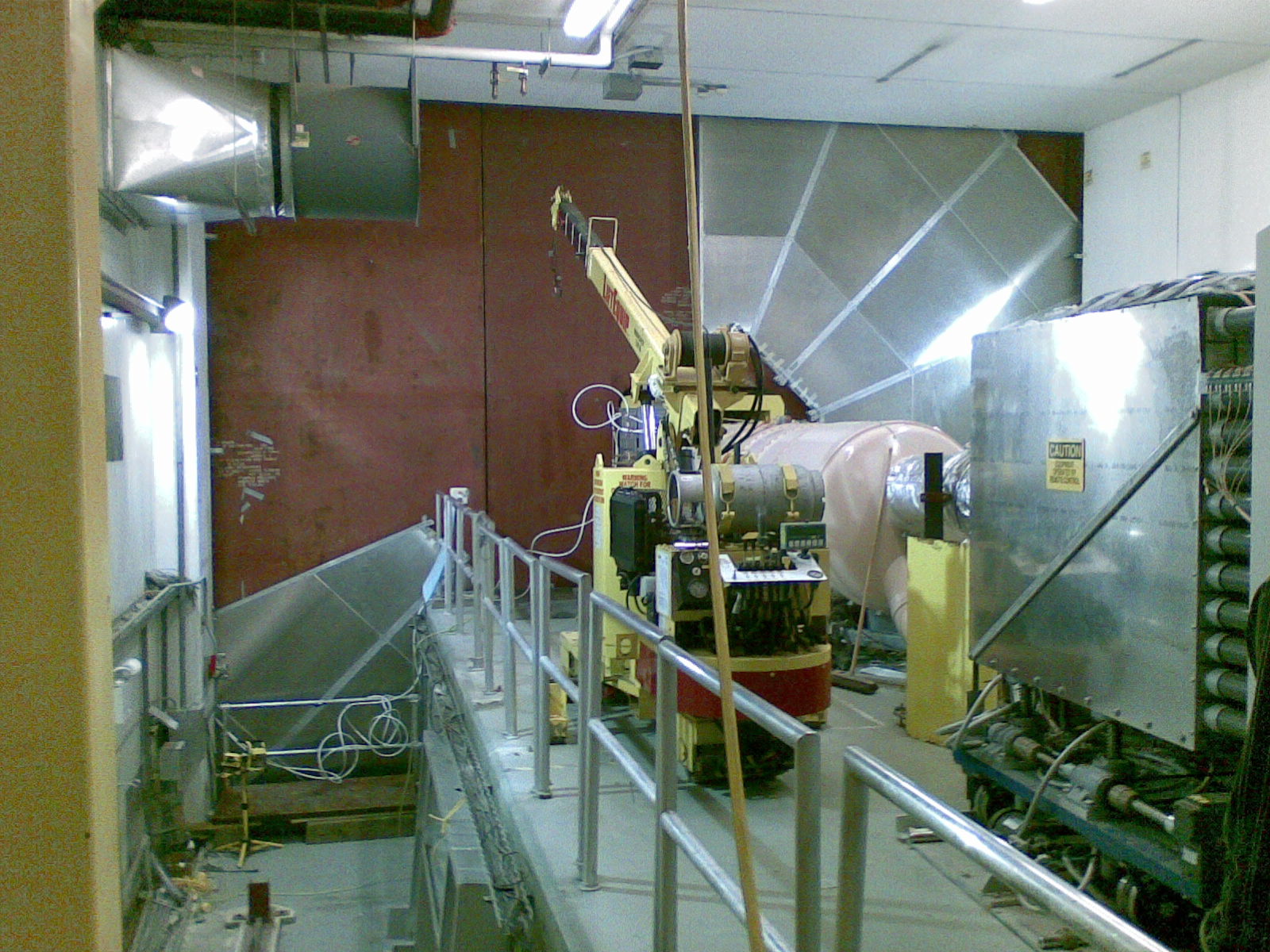
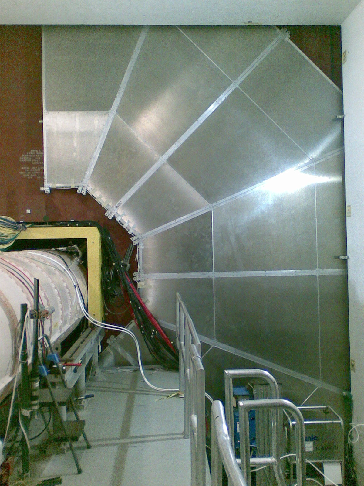
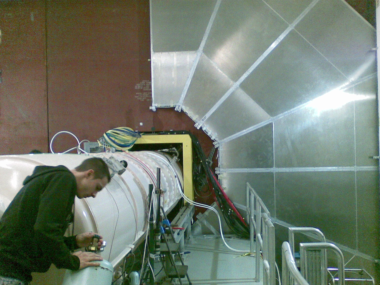
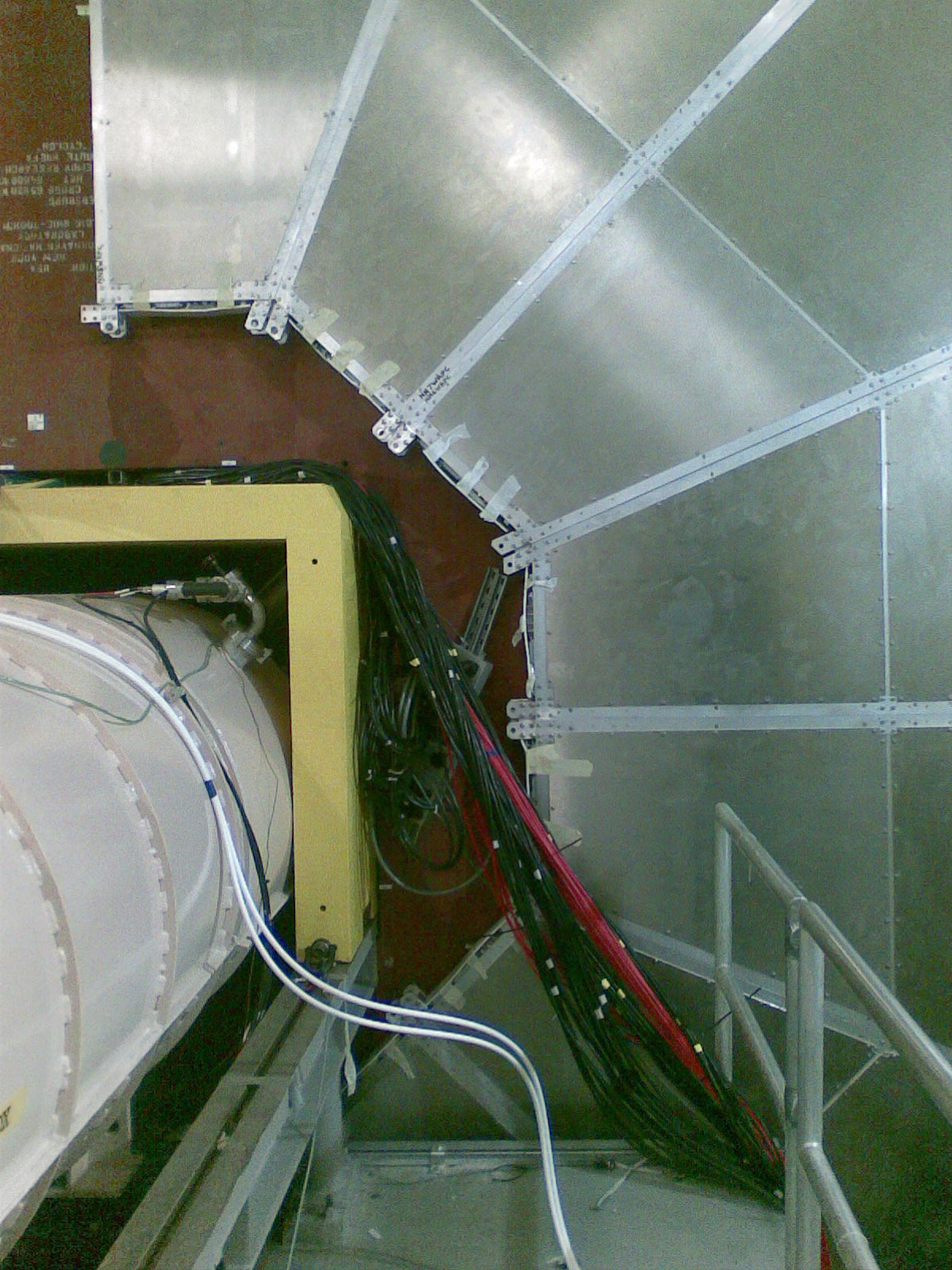
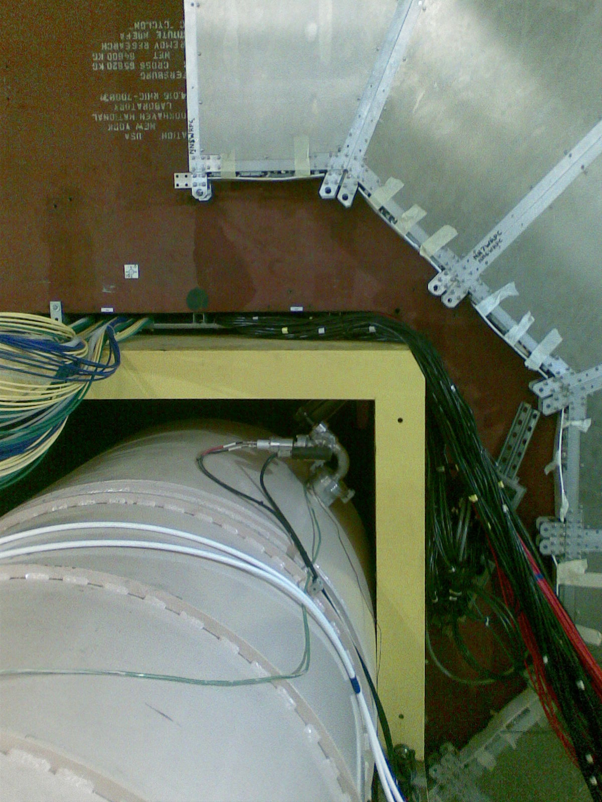
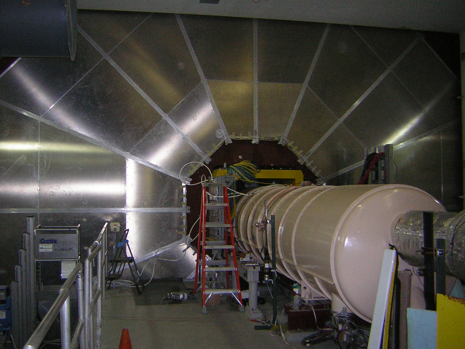
The pictures above show the central detector and magnet of PHENIX. RPC1 huddles close to the magnet, near the Beam Beam Counters (BBCs, also referred to as "flower pots".) RPC1 does not appear in these pictures. They were taken to understand the environment RPC1 would be installed in. These few pictures taken from the RHIC tunnel cannot convey just how tight the space was that RPC3 was installed in. Many other photos were taken showing pipes and other things that interfered with RPC3 and had to be moved.
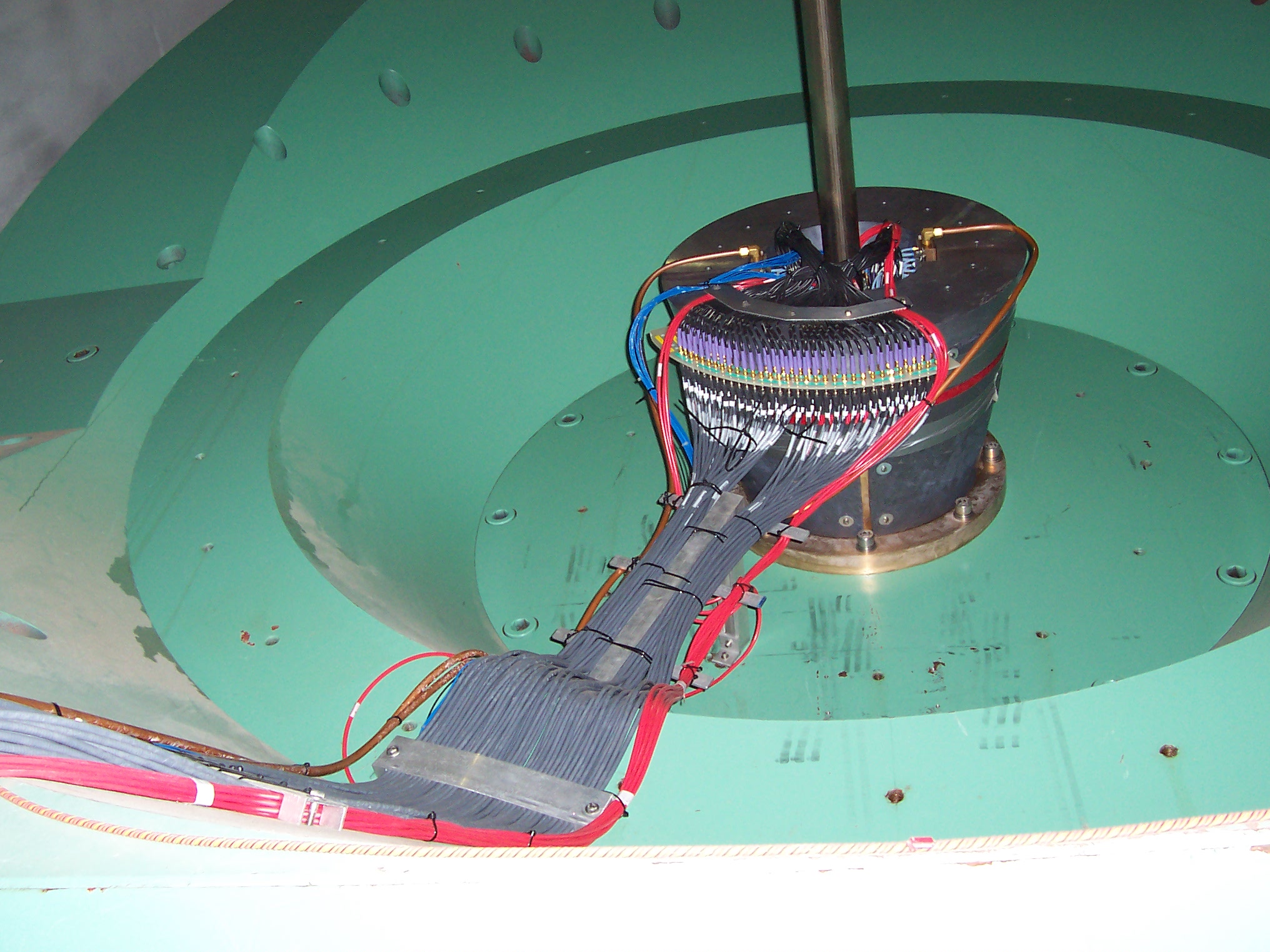
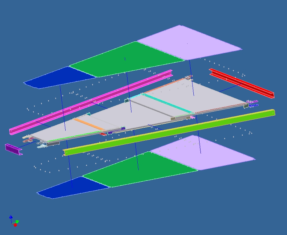
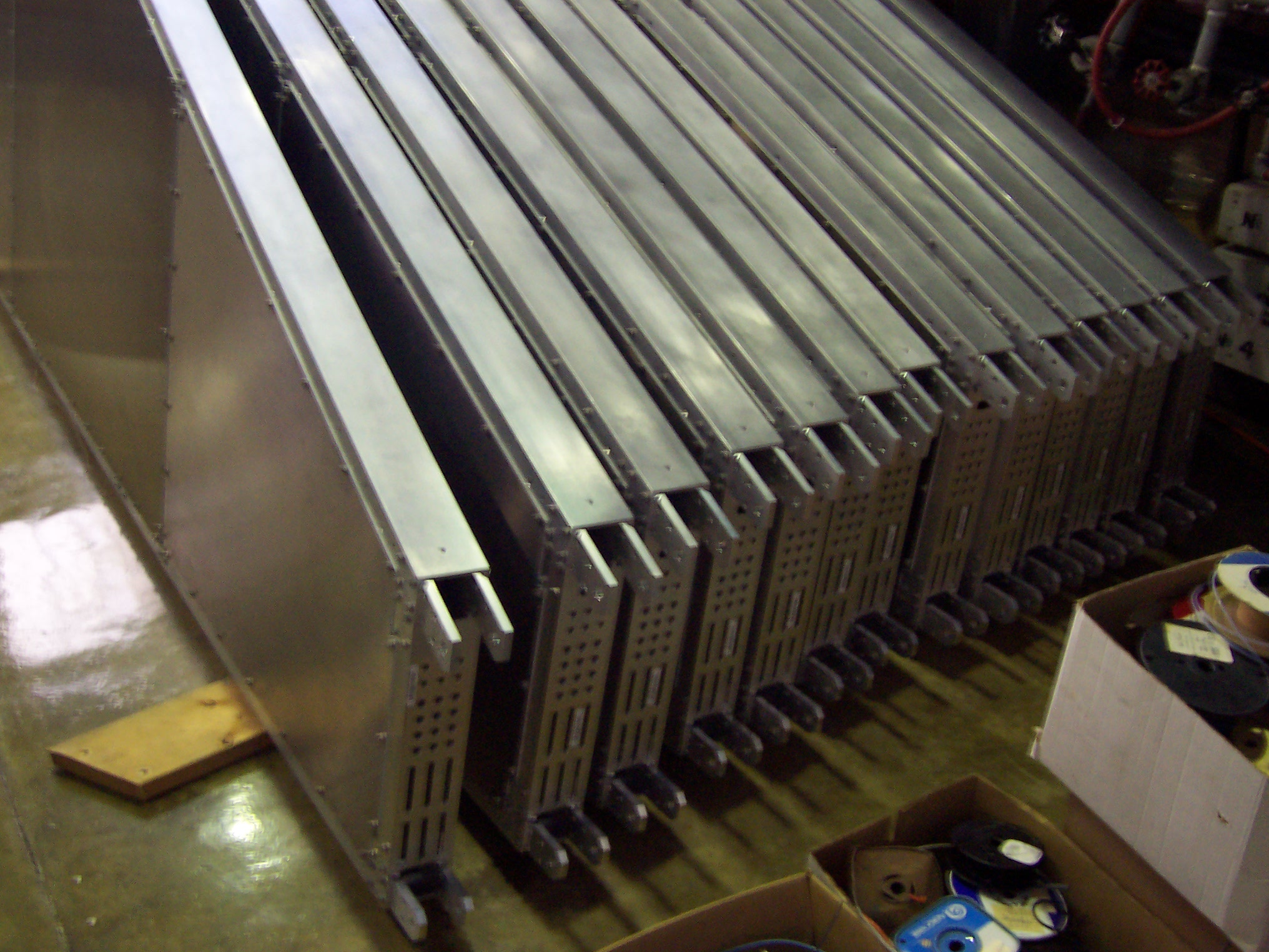
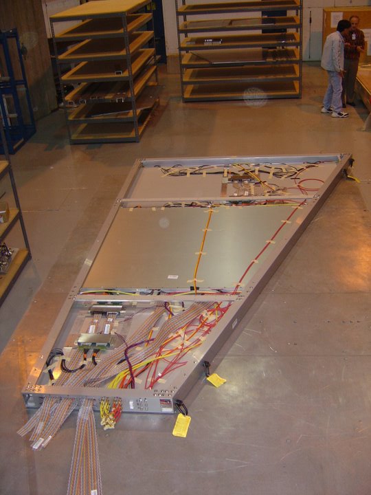
Three different RPC detectors fill the volume inside the half-octant containers. They overlap to allow the active regions inside the detector packages to line up and avoid too much dead space between detectors. Power, signal cables, gas lines and electronics all had to be mounted inside each half-octant along with the detectors.
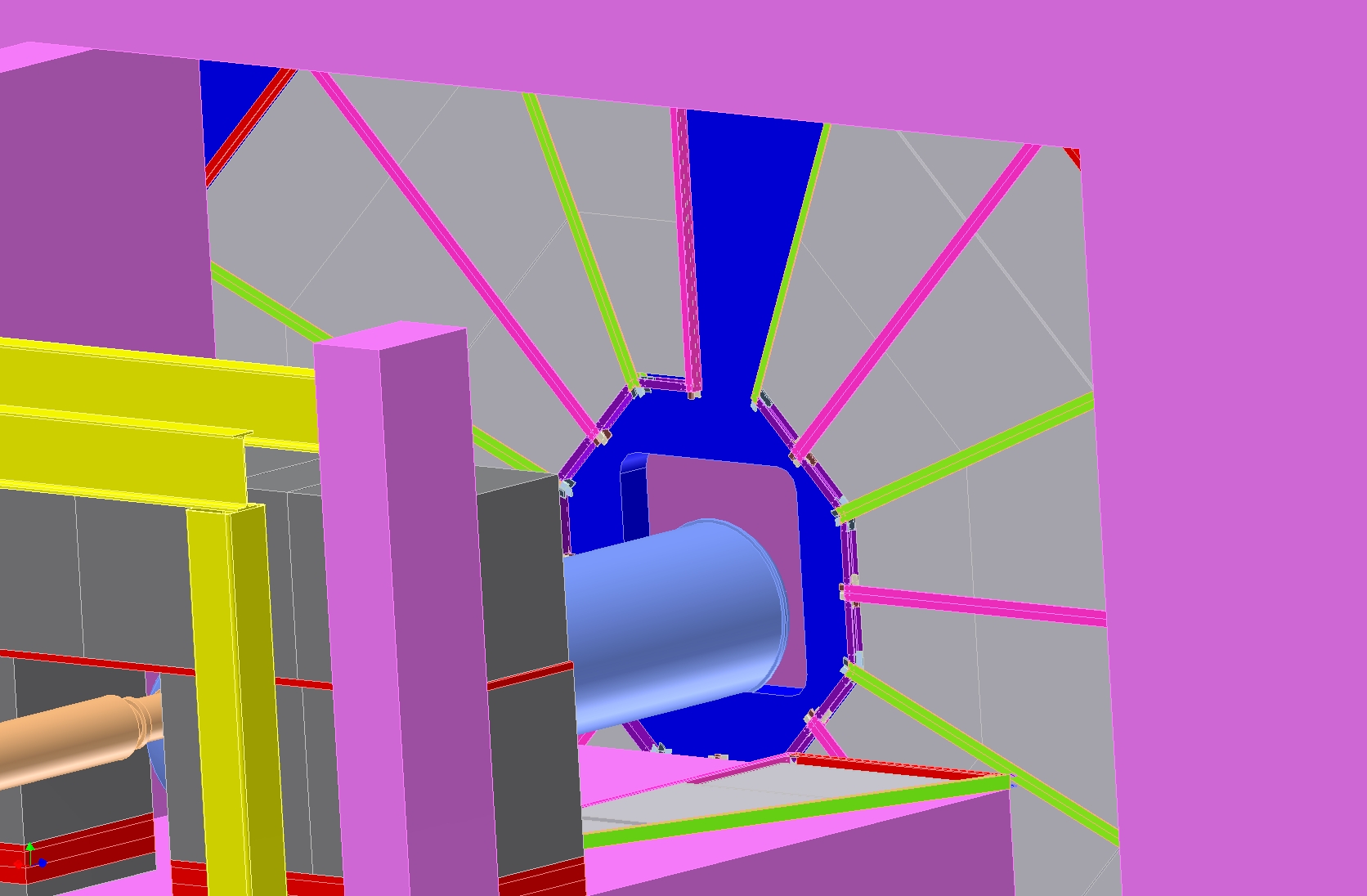
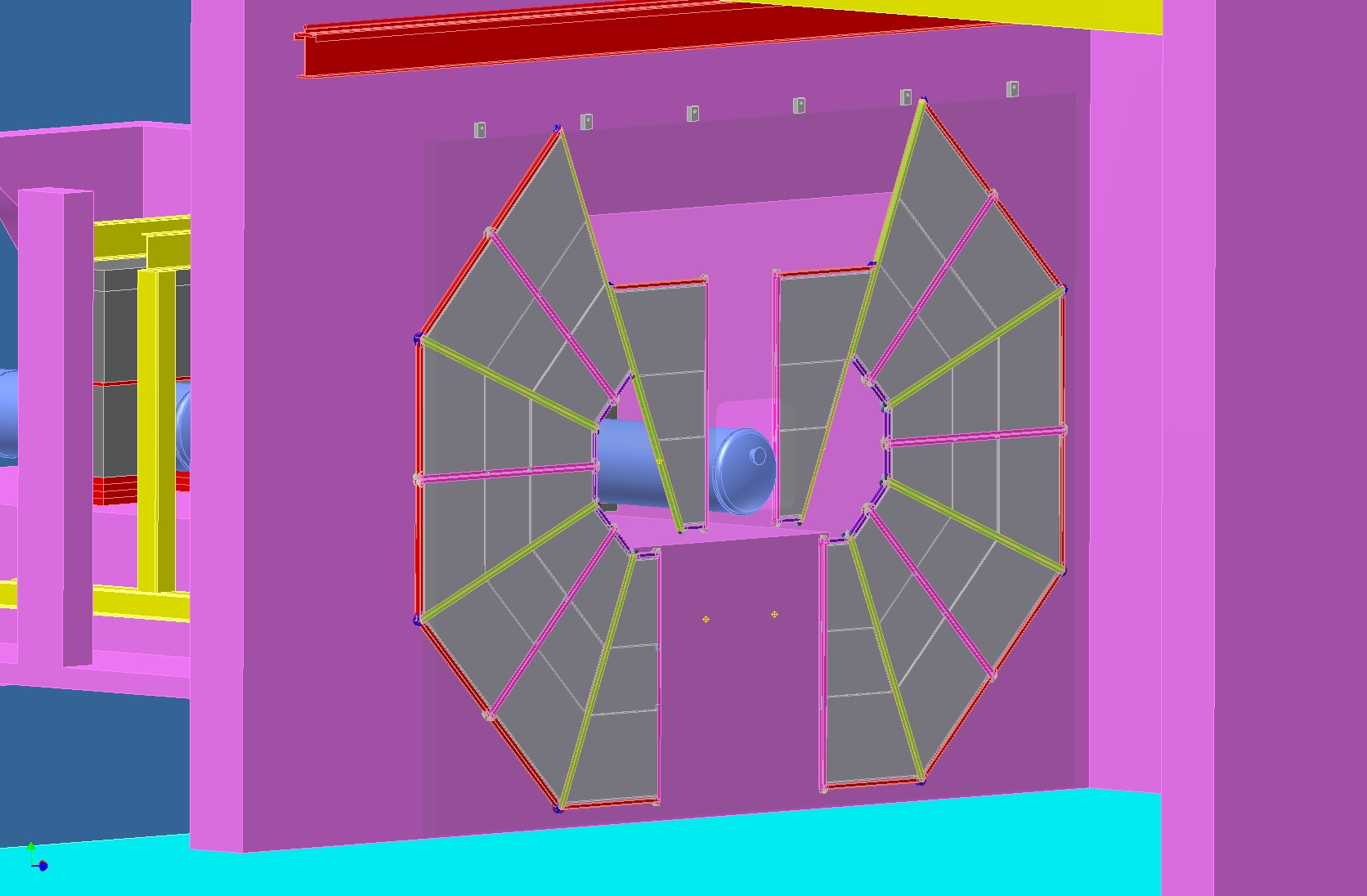
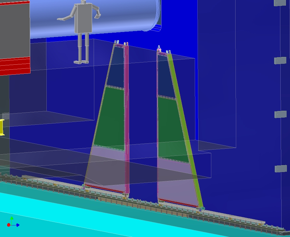
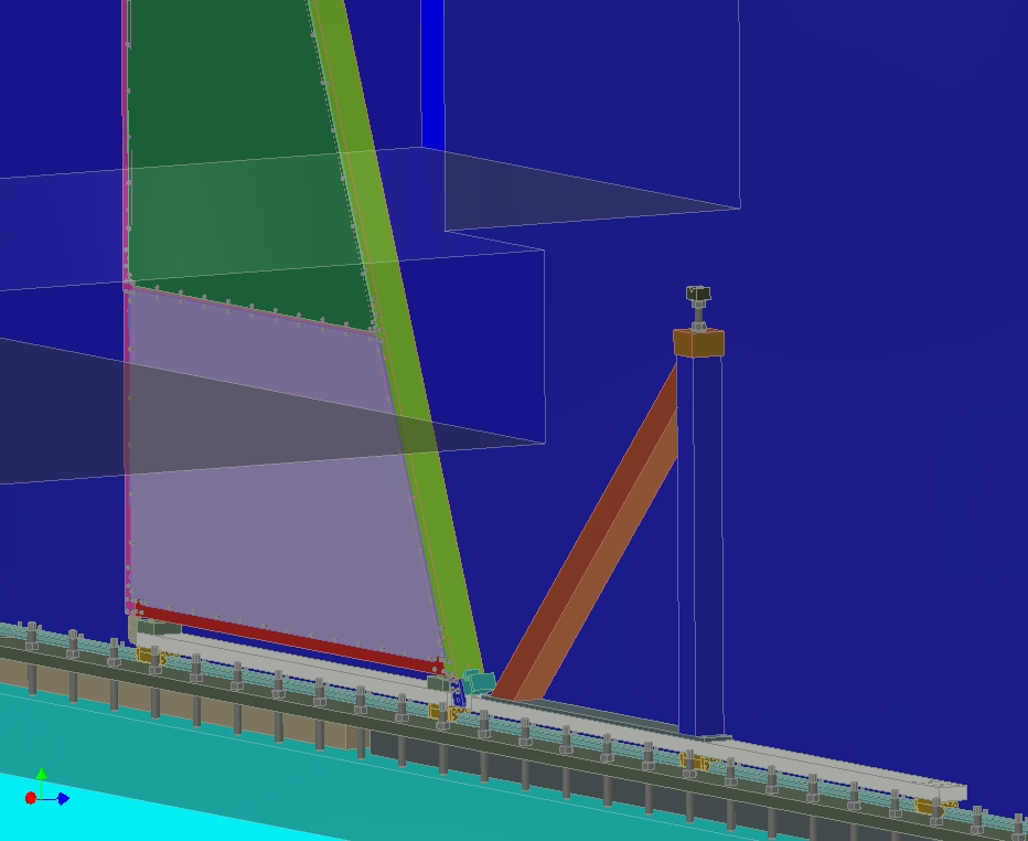
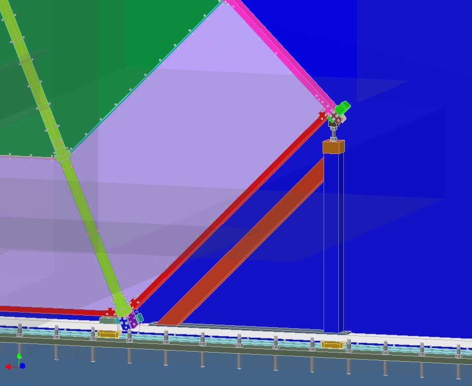
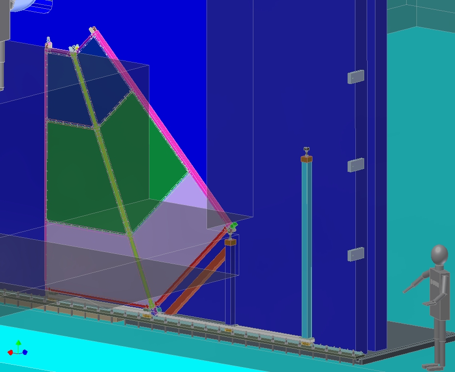
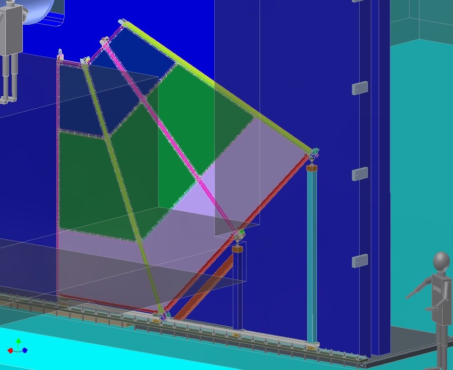
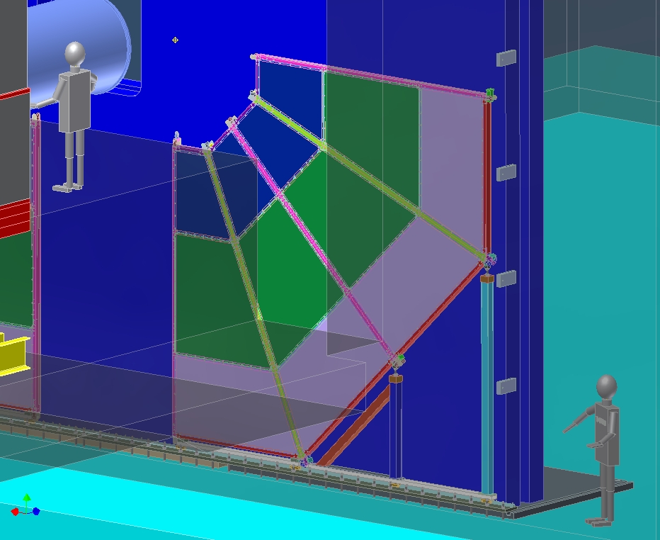
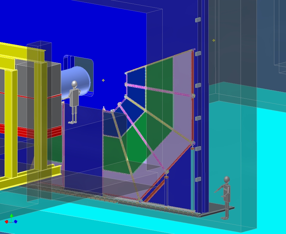
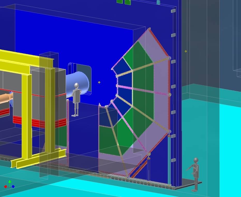
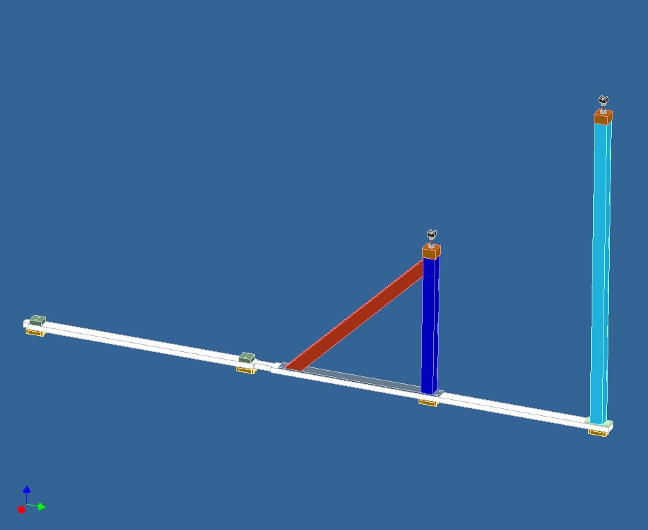
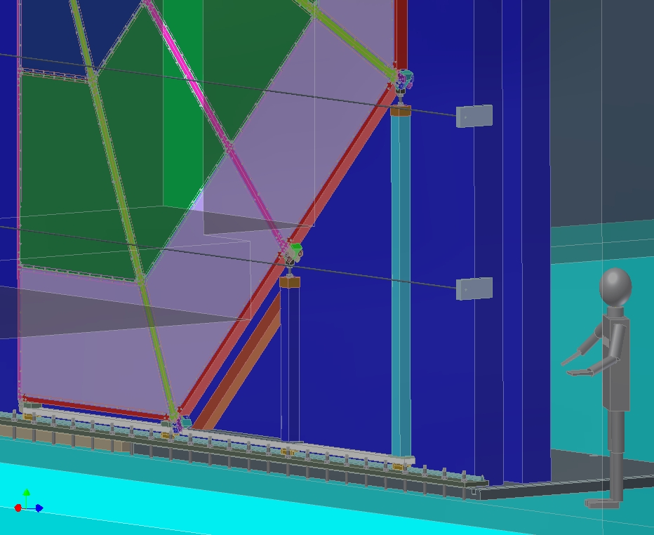
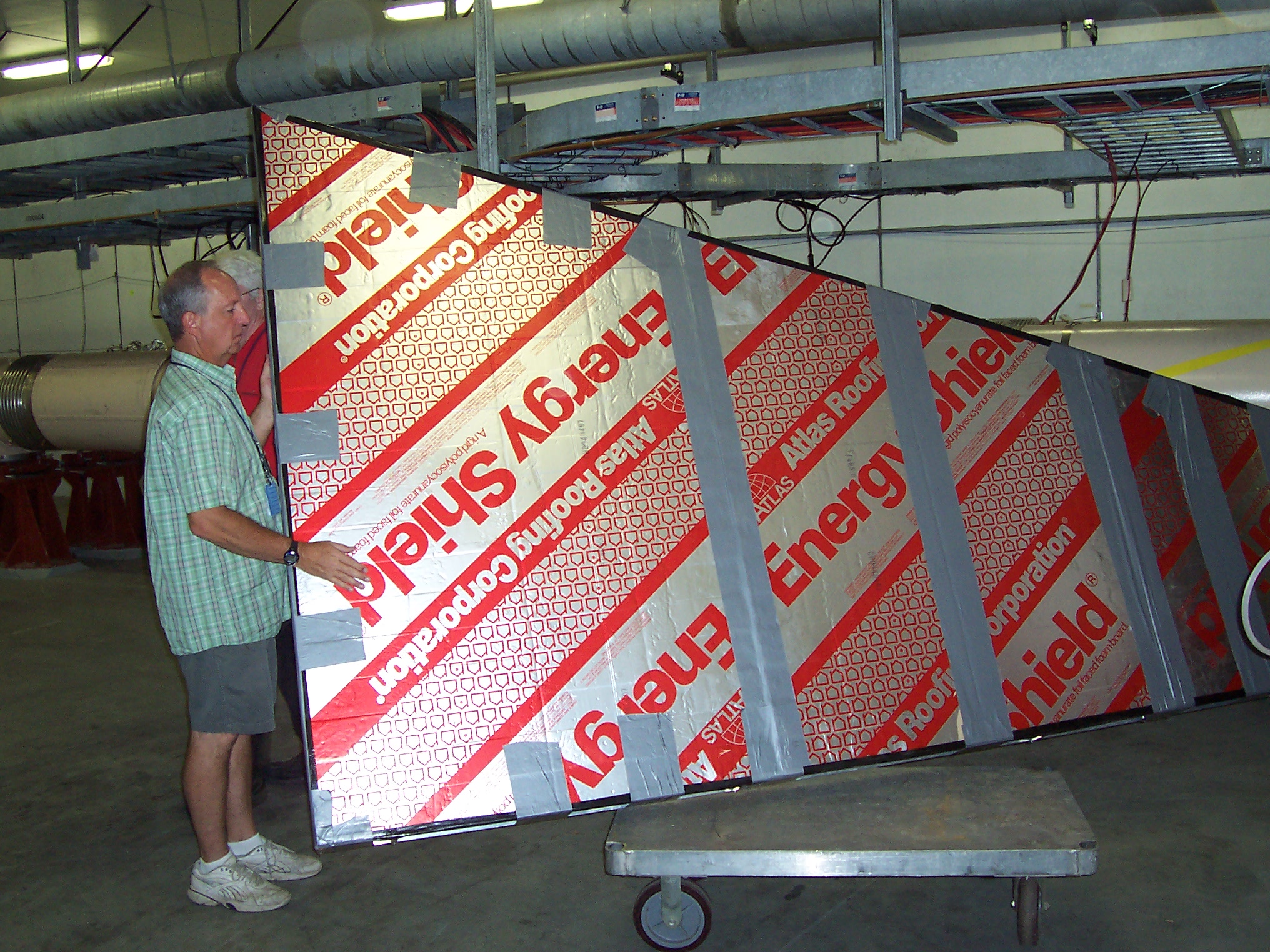
These pictures show the ideas I experimented with to come up with the installation procedure. Getting the top two octants in was the problem. These pictures show why I concluded the two halves of RPC3 had to be built separately and independently and moved together as a final step. That was the only scenario that avoided the top two half-octants from interfering with each other or with the magnet surrounding the beam pipe. The movement of a half RPC3 was the next design challenge. I eventually came up with a "roller skate" concept. RPC3 isn't all that heavy as detectors go, but it is tall and very thin. Ensuring its stability to movement was the challenge.
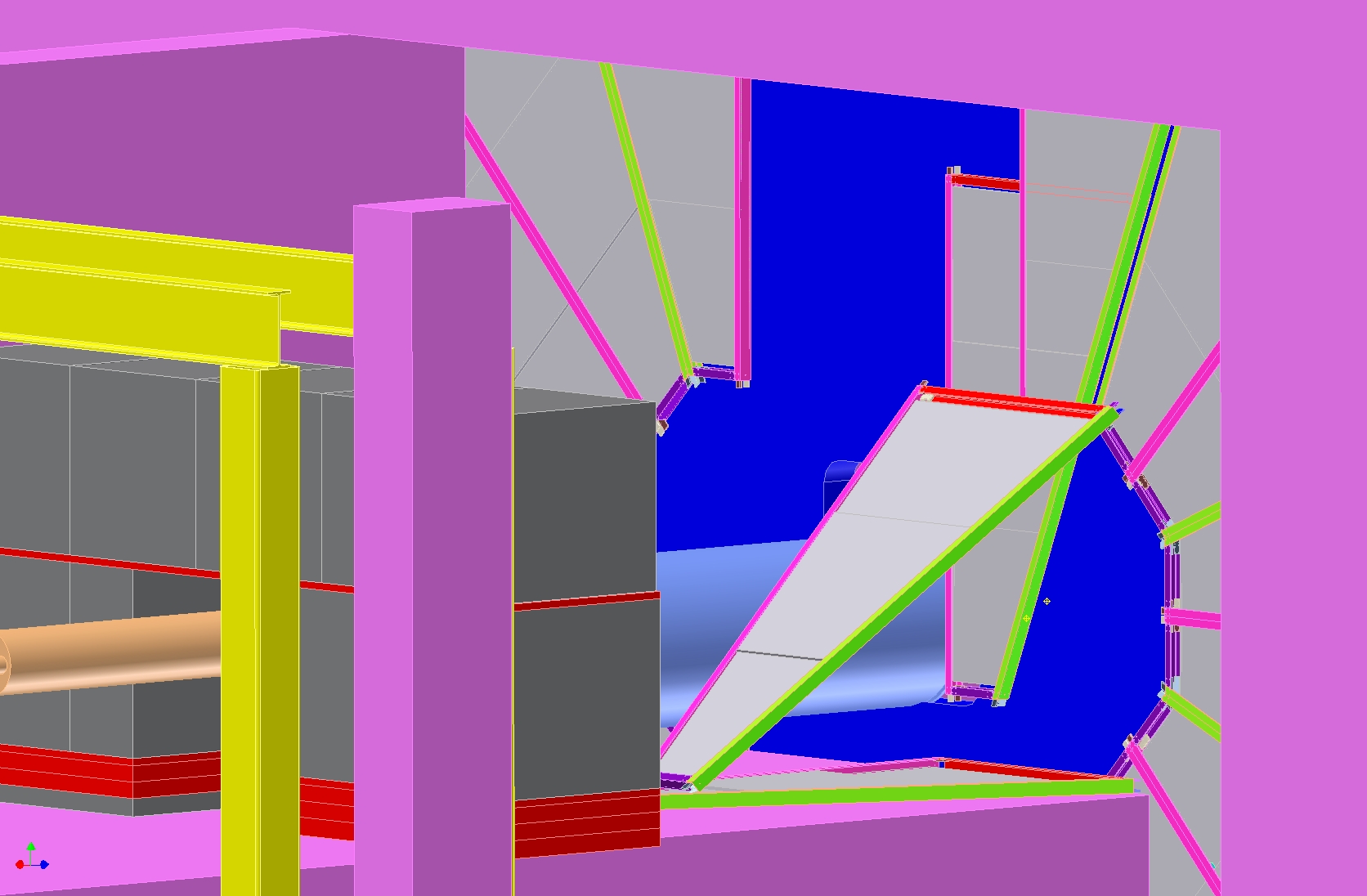
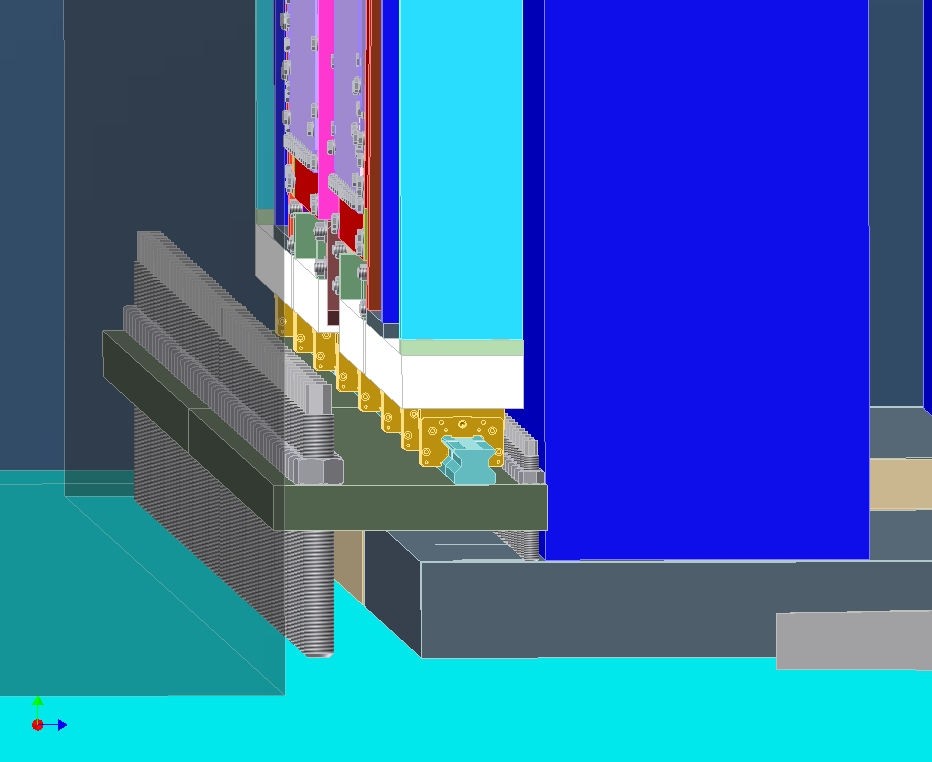
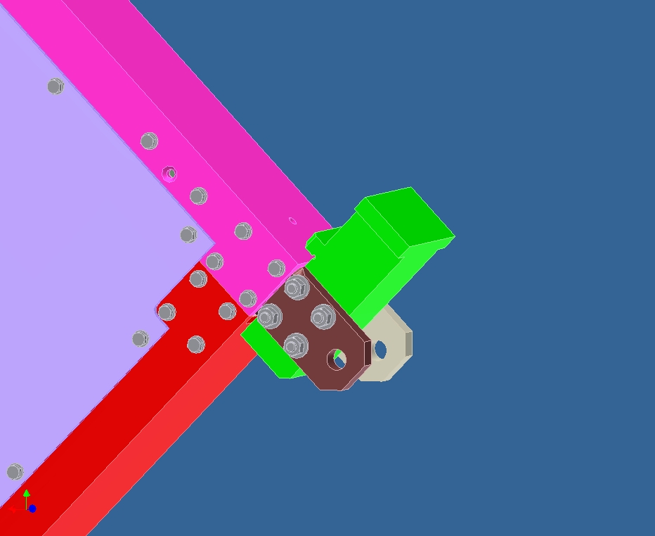
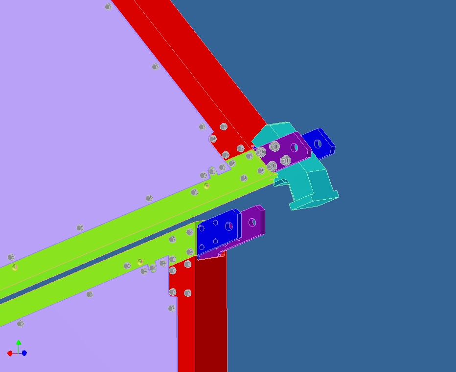
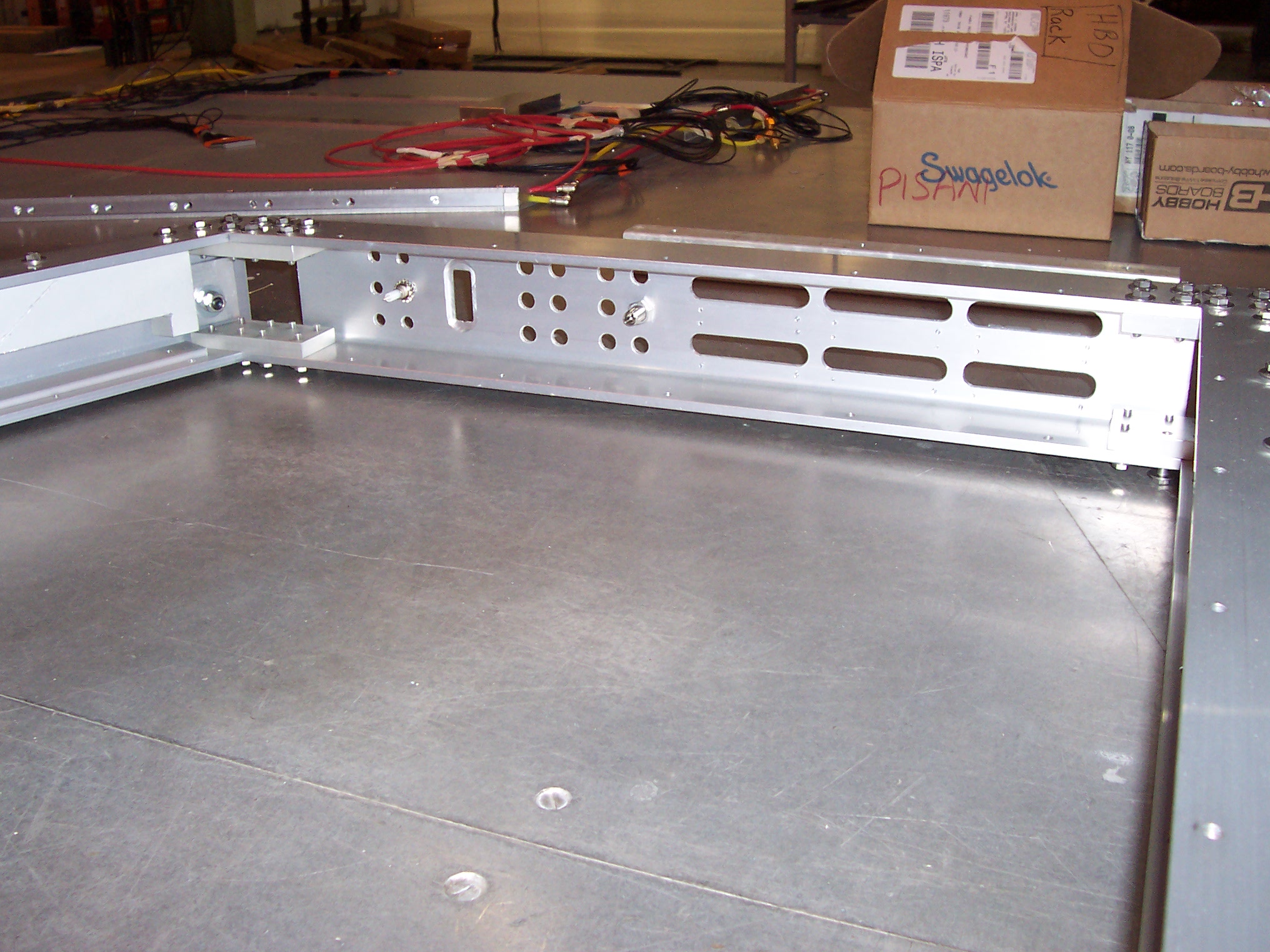
These pictures show the sequence of steps building up each half of a total RPC3 station. Much of the assembly was done almost blind because the gap half octants were lowered into was too narrow to see anything. The wedges were designed with special corner features that locked together as they were lowered onto each other. These features had to be assembled differently between the top and bottom halves. I used the outer diameter corner features to "catch" bottom half octants, so the corner feature was on the lower half octant. On the top half these same outer diameter corners became hangers, so the wedge being lowered had to have the corner block feature.
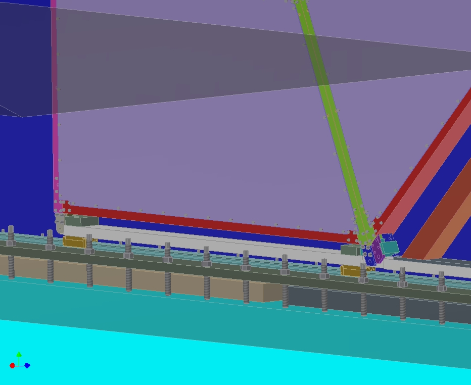
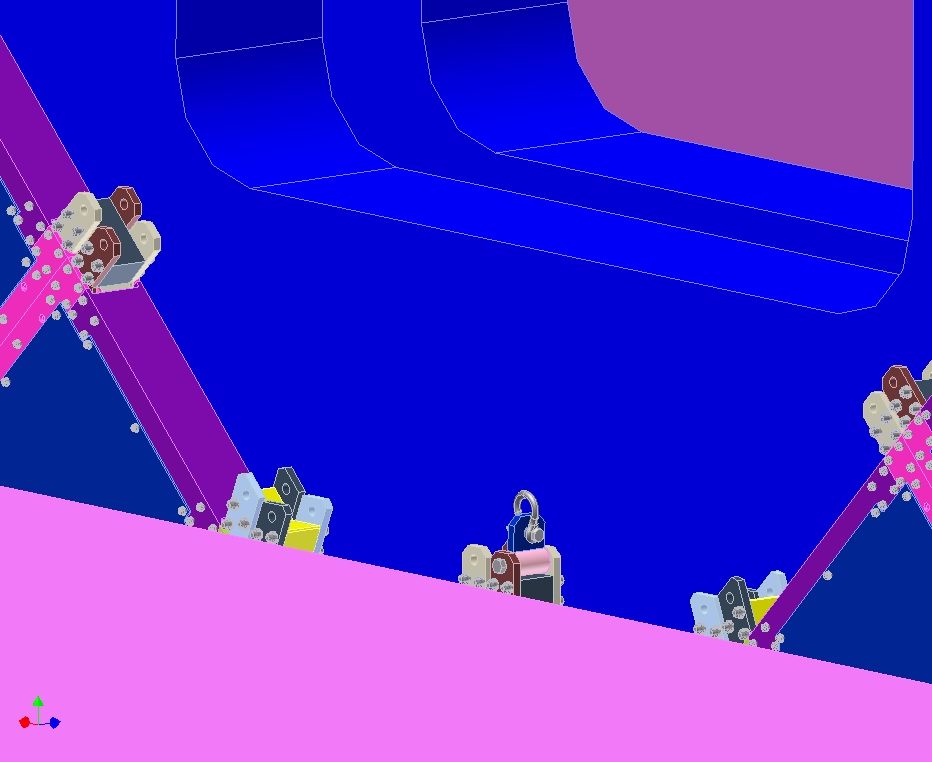
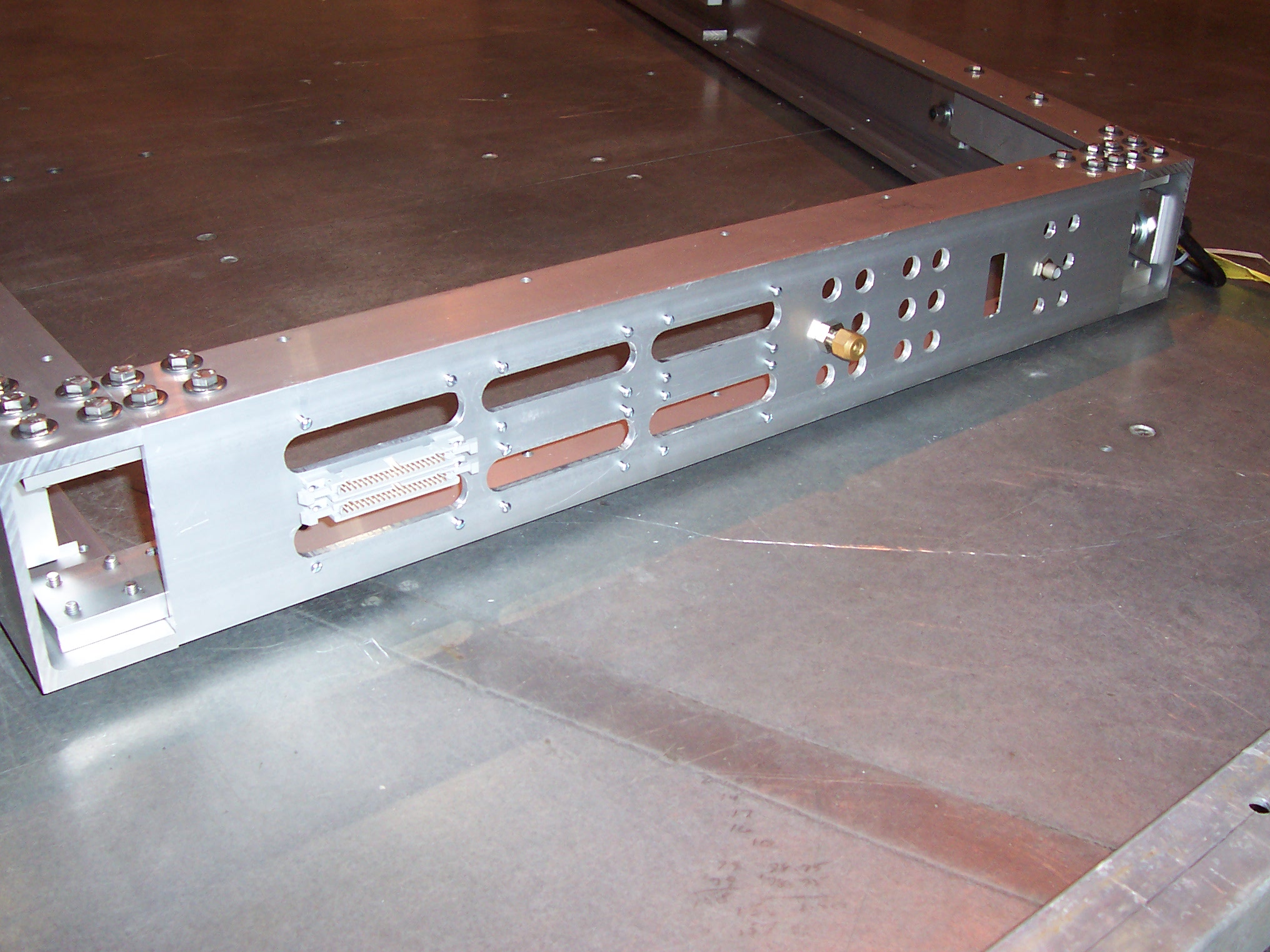
These pictures show closer views of the roller skate that supports each half detector.
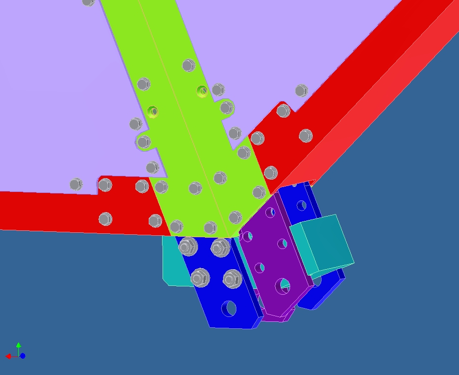
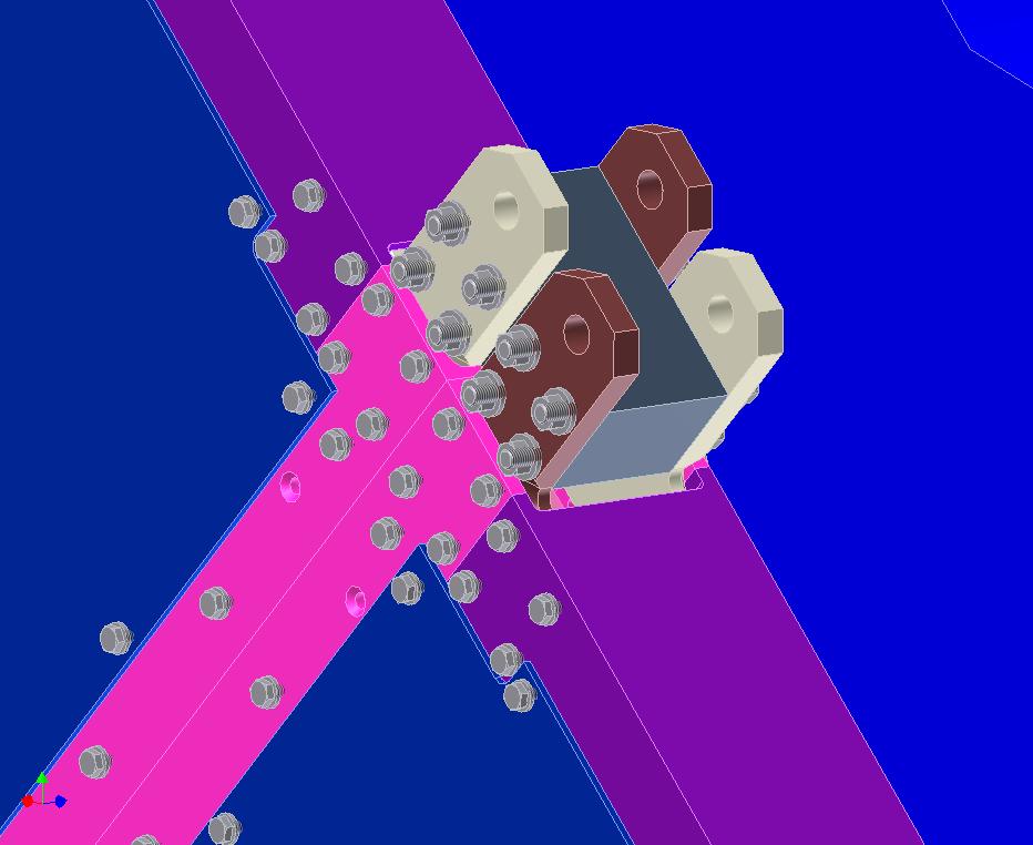
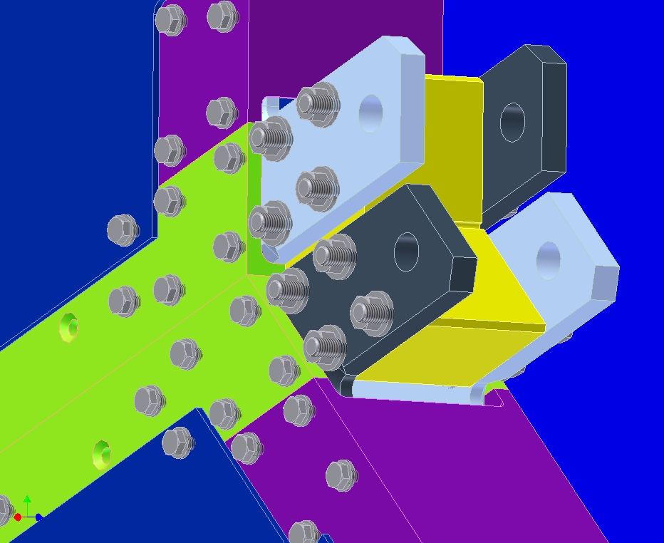
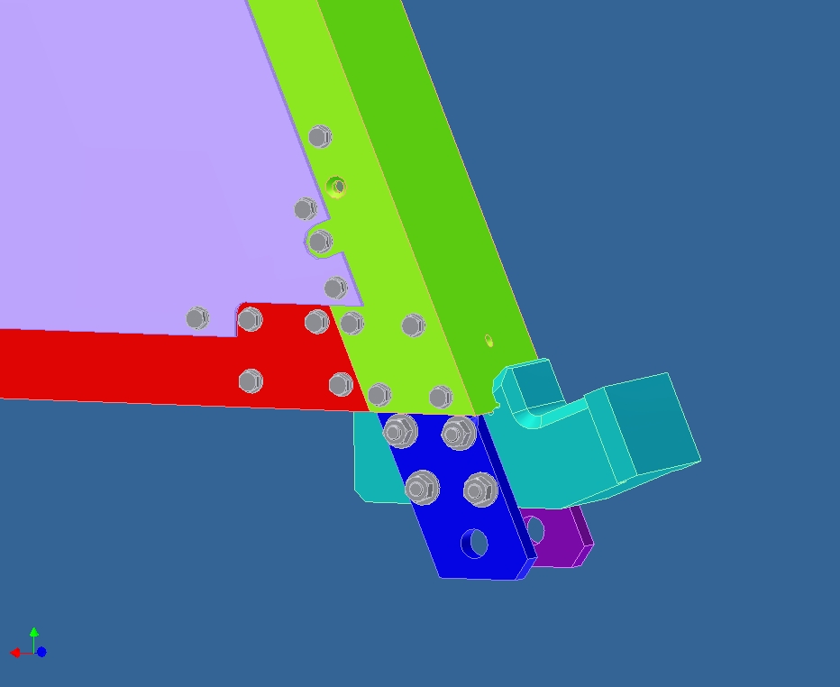
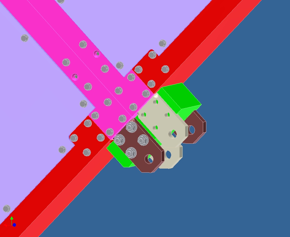
These pictures show the corner locking features that each wedge had to engage the one below it. The ID and OD corners of the wedges had to be bolted together because the top half of the detector overhangs the bottom half and puts some connections in tension. If each wedge is not sufficiently tied to the one below it the entire assembly can collapse.
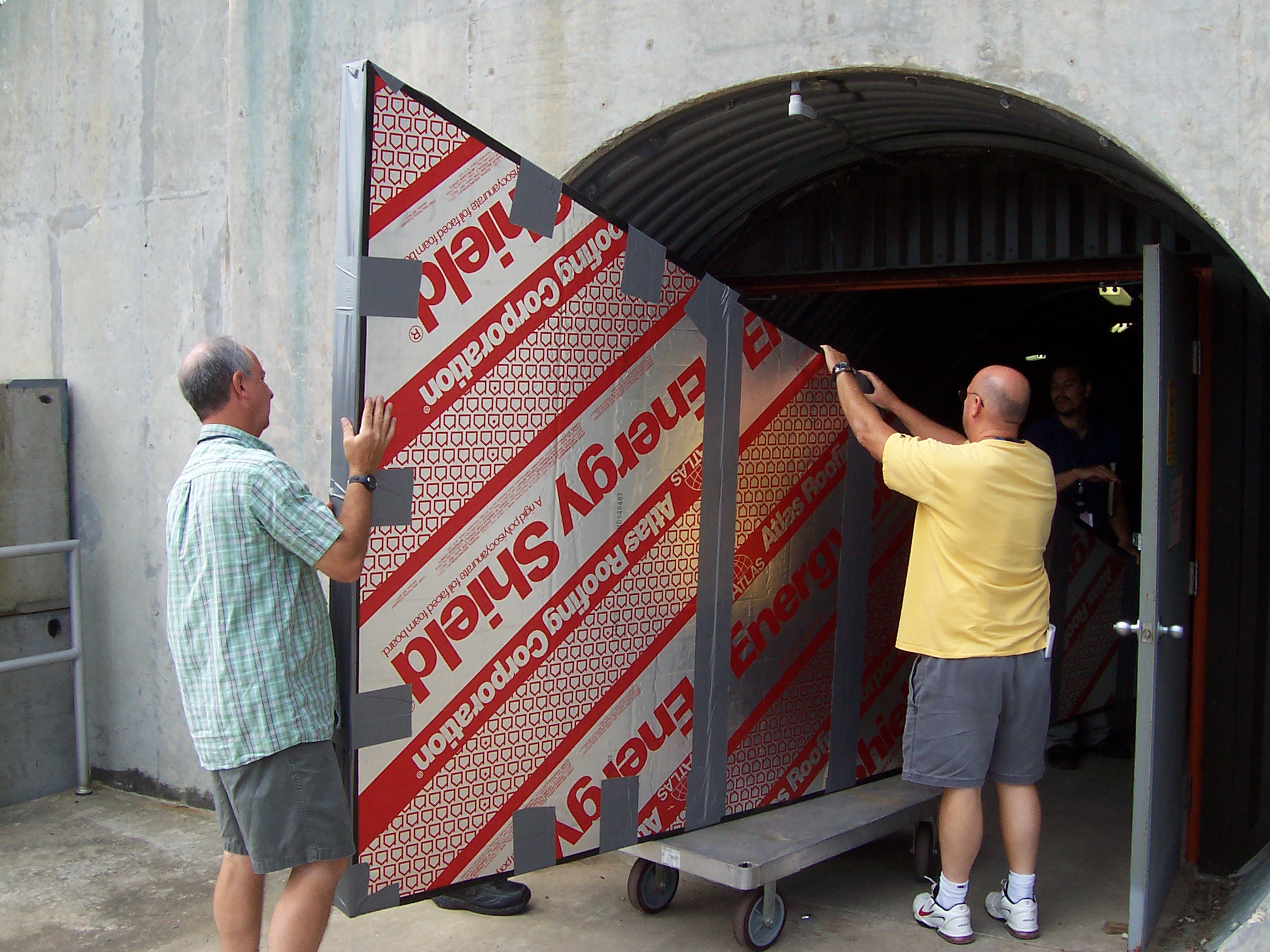
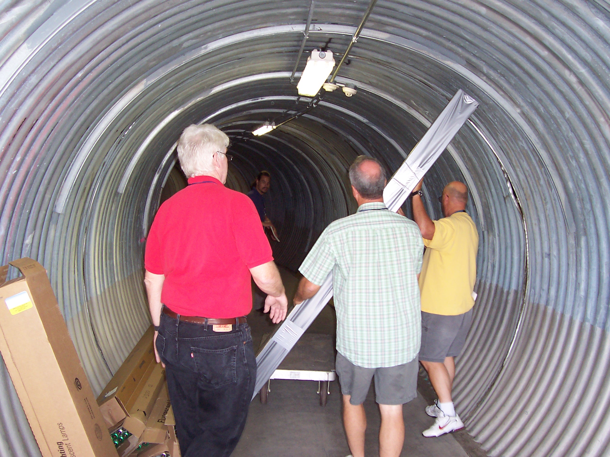
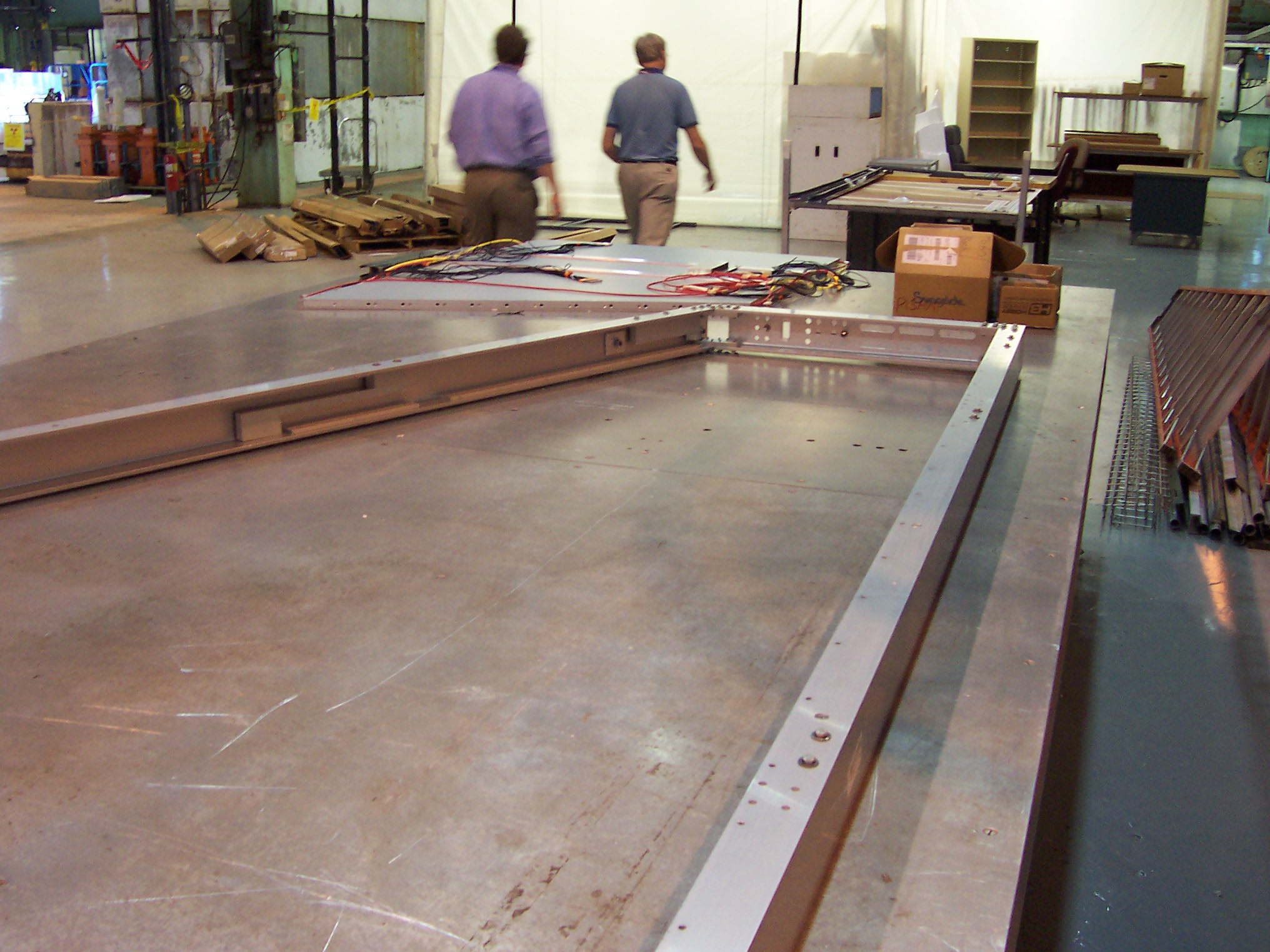
Don Lynch and his technicians built a full scale half-octant mock up so that we could test whether or not the wedges could make it all the way from the entrance door of the tunnel to the gap between the tunnel floor and the PHENIX detector hall. Many obstacles and shielding blocks had to be temporarily removed from the tunnel to make a continuous path.
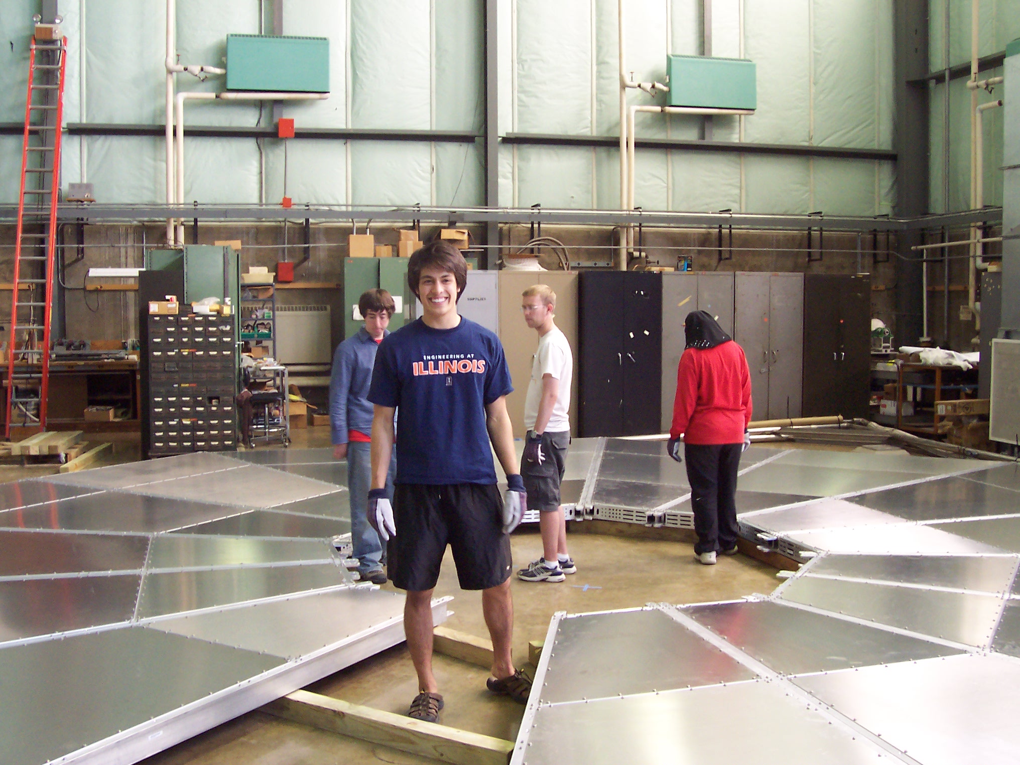
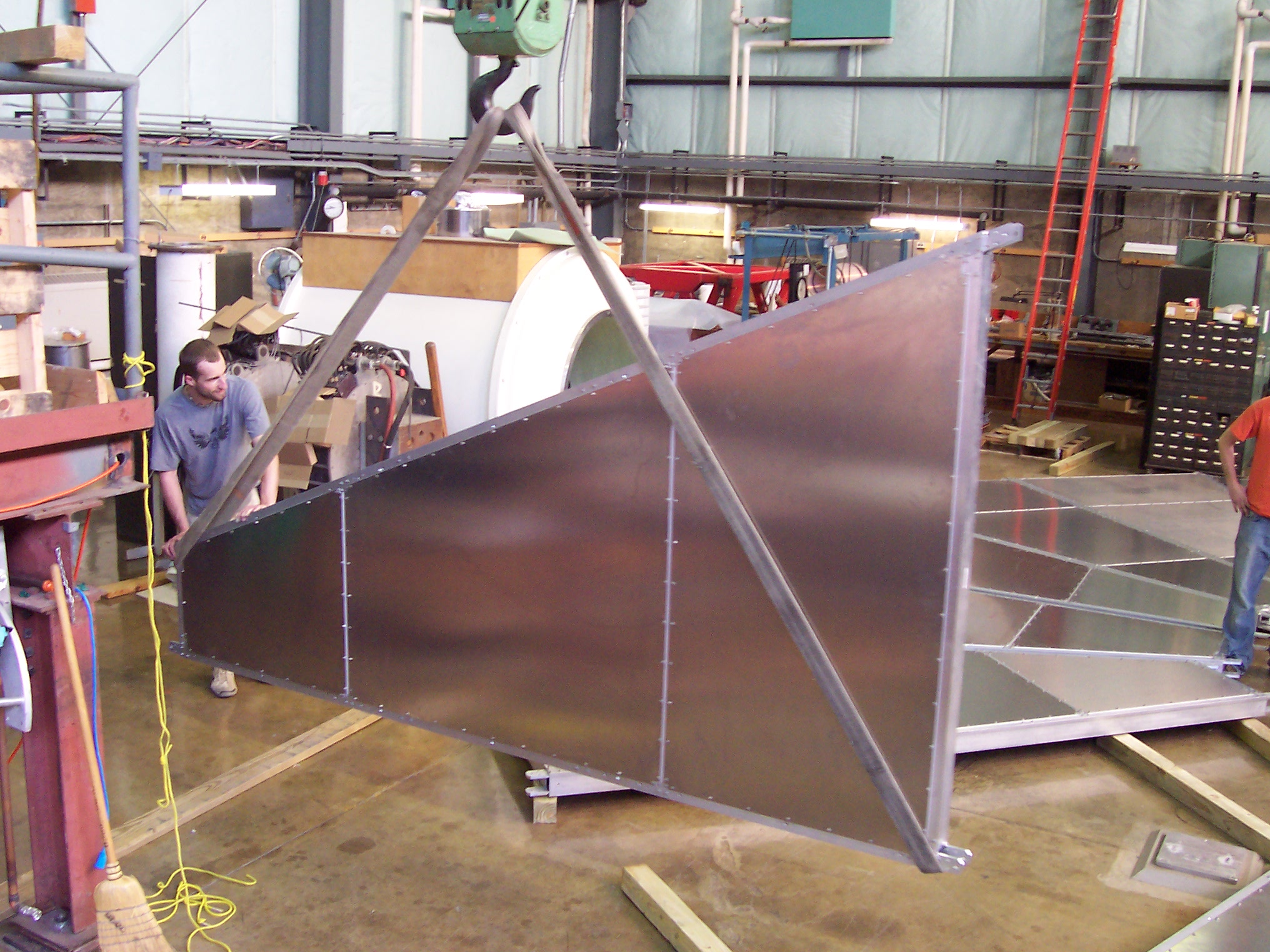
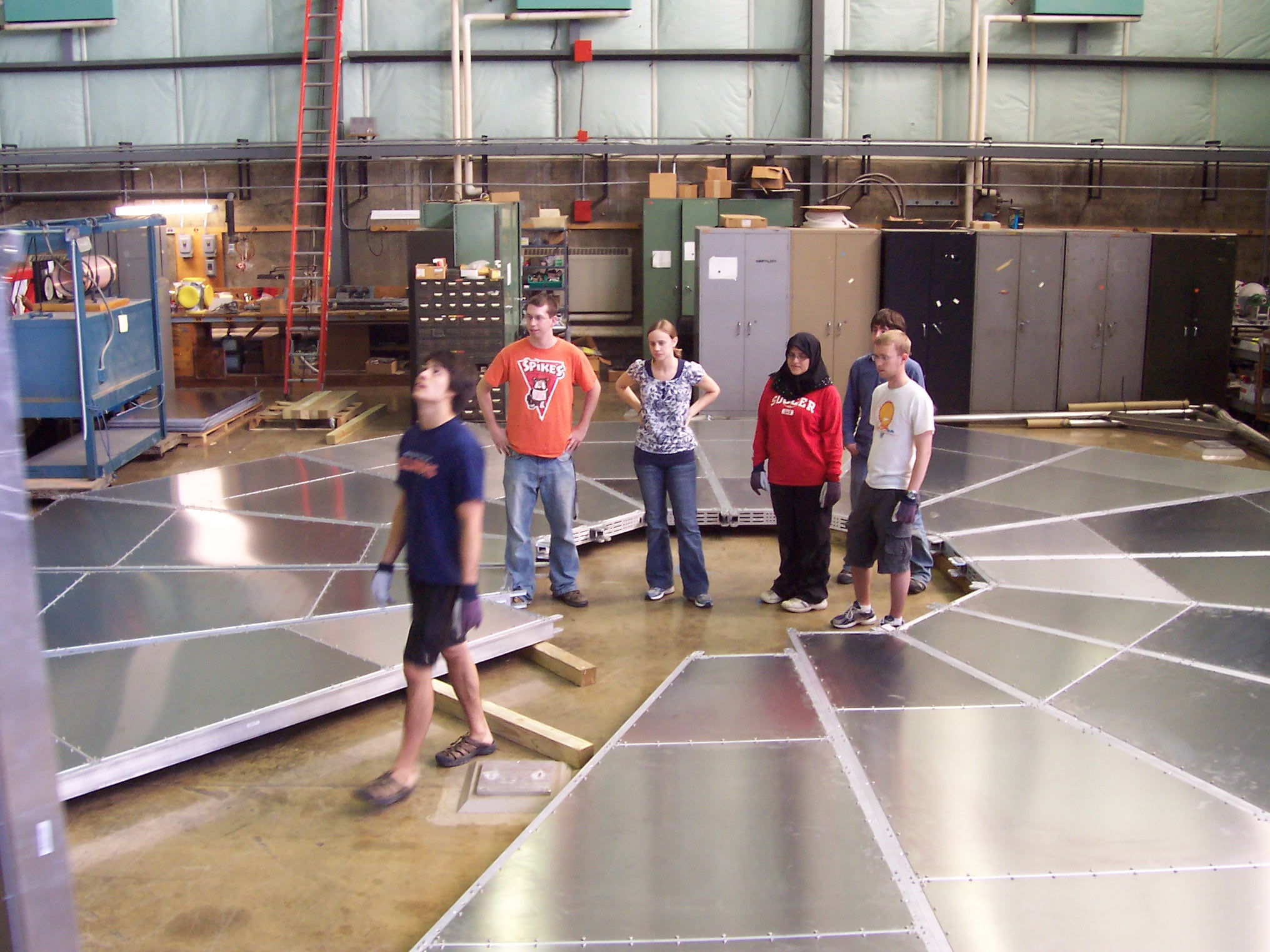
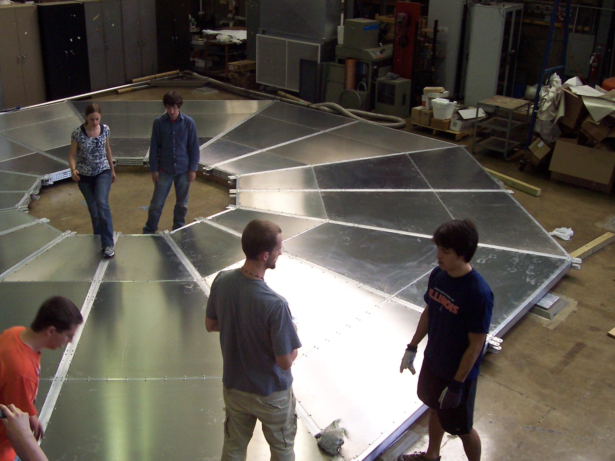
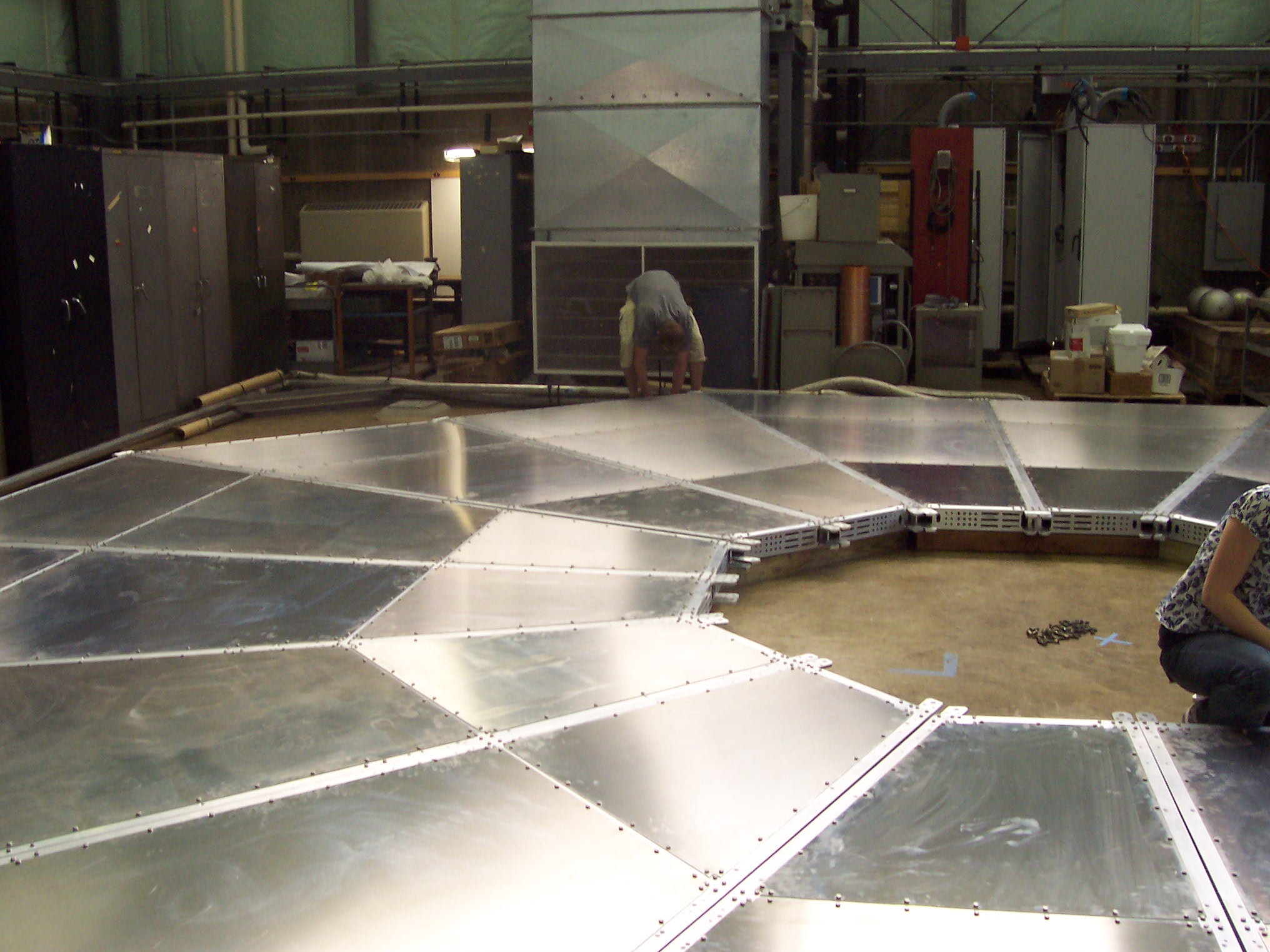
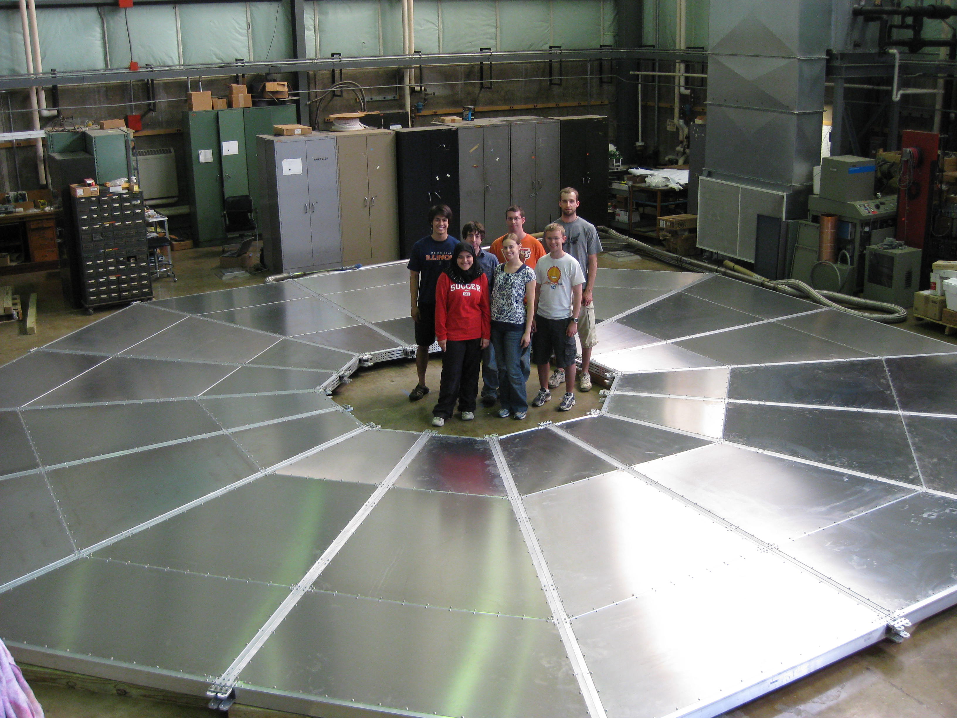
I was privileged to be present at the first assembly of all the half octants in an RPC3 station on the floor in the NPL barn at UIUC. We learned just how well the aluminum support cans were fabricated in China. Everything went together exactly as hoped.
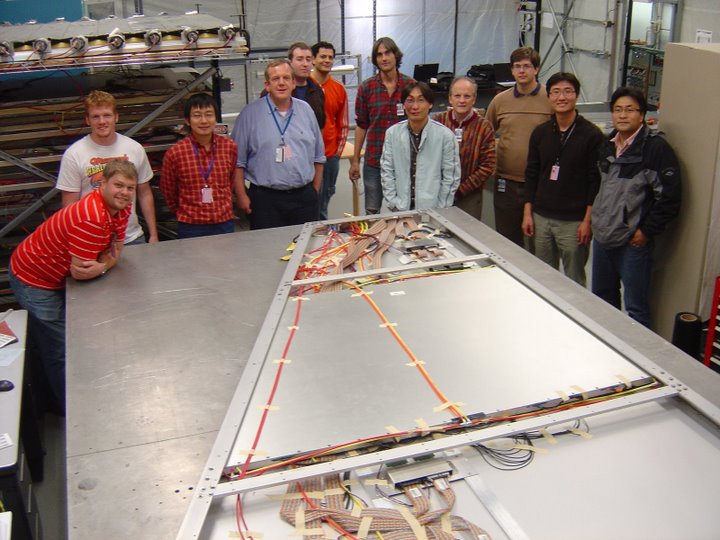
There was a factory at BNL to assemble the RPC detectors into the half octant containers, wire and plumb them. Finished RPCs were tested with cosmic rays to make sure everything was working.
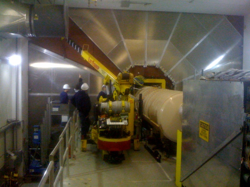
I am grateful to Don Lynch for providing me with these photos of the installation of the half octants in the tunnel. The machine that saved the day was a walk-behind crane that Charlie Pearson had. Don designed a special attachment head for the crane to lift half-octants in place. I scratched my head for a very long time about how this job would be done. Charlie's machine made it possible for minimal expense.
Back to the Bartoszek Engineering Projects Page
Back to the Bartoszek Engineering Home Page
|